Long-range proximity sensors are critical components in industrial automation, material handling, and security systems. Their ability to detect objects without physical contact over considerable distances ensures operational efficiency and safety. However, like all electronic devices, they are susceptible to failure. This guide provides a systematic approach to diagnosing and repairing common issues in long-range proximity sensors, focusing on inductive, capacitive, and ultrasonic types.
The first step in any repair process is accurate diagnosis. Begin by verifying the symptoms. Common failures include no output signal, intermittent detection, reduced sensing range, or false triggering. Before disassembling the sensor, perform a basic environmental check. Ensure the sensor is free from excessive dust, moisture, or metallic debris, which can interfere with its field. Check the power supply with a multimeter; voltage outside the specified range (commonly 10-30V DC) can cause malfunction. Inspect the wiring and connectors for corrosion, loose connections, or physical damage. A broken cable near the connector is a frequent culprit.
If power and wiring are correct, proceed to functional testing. Use a target object specified by the manufacturer (usually a standard metal plate for inductive sensors) and measure the output. For a normally open (NO) sensor, the output voltage should switch from high to low (or vice versa for PNP/NPN types) when the target enters the sensing range. An oscilloscope can reveal signal integrity issues like noise or slow switching. If the output is dead, the internal oscillator or amplifier circuit may have failed. Reduced range often points to a weakened oscillator coil in inductive sensors or deteriorating transducer elements in ultrasonic sensors.
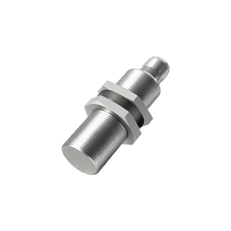
For internal repair, power down and isolate the sensor. Carefully open the housing, noting the sealing method if the unit is rated IP67 or higher. Internal inspection should focus on several key areas. Examine the sensing face for cracks or coating damage. Check the core coil in inductive sensors for discoloration or broken windings. In capacitive sensors, inspect the electrode plate for contamination. Ultrasonic sensors require a check of the piezoelectric transducer for physical damage. Use a magnifying glass to look for cracked solder joints, burnt components, or blown fuses on the printed circuit board (PCB). A thermal camera or a simple touch test (when powered briefly) can identify overheating components like voltage regulators or output transistors.
Component-level repair requires schematic diagrams, which are often proprietary. However, common failures are replaceable. A shorted output transistor (often a MOSFET) is a common failure due to overcurrent or inductive load spikes. Desolder and replace it with an identical or superior specification part. Faulty voltage regulators can cause low or unstable supply to the ICs. Electrolytic capacitors can dry out and fail, leading to power supply ripple; replace them with low-ESR types. For sensors with potentiometers for range or sensitivity adjustment, contact cleaner can resolve erratic behavior. If the oscillator coil is damaged, replacement typically requires an identical part from the manufacturer or a salvaged unit.
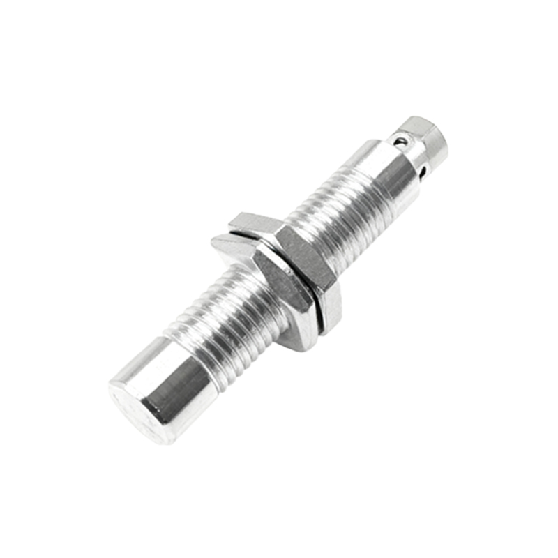
After replacing components, reassemble the sensor carefully, ensuring the original environmental seals are intact. Perform a post-repair calibration if possible. Many sensors have a teach-in function or a calibration potentiometer. Use the specified target at the exact recommended distance to set the sensing point. Test the sensor across its entire temperature and voltage operating range to ensure stability. Finally, document the failure mode, replaced components, and test results for future reference.
Preventive maintenance is crucial. Regularly clean the sensor face, ensure electrical connections are tight, and protect sensors from mechanical vibration and voltage surges using appropriate suppressors. Understanding the root cause of failure—whether electrical overload, environmental stress, or mechanical impact—can guide improvements in installation and prolong service life. While not all sensors are economically repairable, especially sealed units, this systematic approach can restore functionality in many cases, reducing downtime and replacement costs.