Proximity sensors are indispensable components in modern industrial automation, robotics, and countless electronic systems. Their ability to detect the presence or absence of an object without physical contact ensures reliability, longevity, and precision. The manufacturing process of these sensors is a sophisticated blend of materials science, precision engineering, and stringent quality control. This article delves into the core production stages, from initial design to final testing, providing electrical engineers with a detailed overview of how these critical devices are made.
The journey begins with the Design and Prototyping Phase. Engineers utilize advanced CAD software to create detailed schematics and 3D models. This stage defines the sensor's type (inductive, capacitive, photoelectric, or ultrasonic), sensing range, housing material (typically nickel-plated brass, stainless steel, or PBT plastic), and electrical specifications (e.g., NPN/PNP output, voltage range). Prototypes are built and subjected to initial functional tests to validate the design against the target application's requirements, such as response time, temperature tolerance, and environmental resilience (IP ratings).
Following design validation, the process moves to PCB Assembly and Core Component Fabrication. For inductive and capacitive sensors, this involves the precise winding of coils. High-precision automated winding machines layer copper wire onto a ferrite core, a critical step that directly influences the sensor's sensitivity and sensing distance. The wound coil is then potted or encapsulated to protect it from vibration, moisture, and thermal stress. Simultaneously, the application-specific integrated circuit (ASIC) or oscillator circuit board is populated using Surface Mount Technology (SMT). Pick-and-place machines accurately position micro-components like oscillators, amplifiers, and output transistors onto the PCB, which is then passed through a reflow soldering oven to create permanent electrical connections.
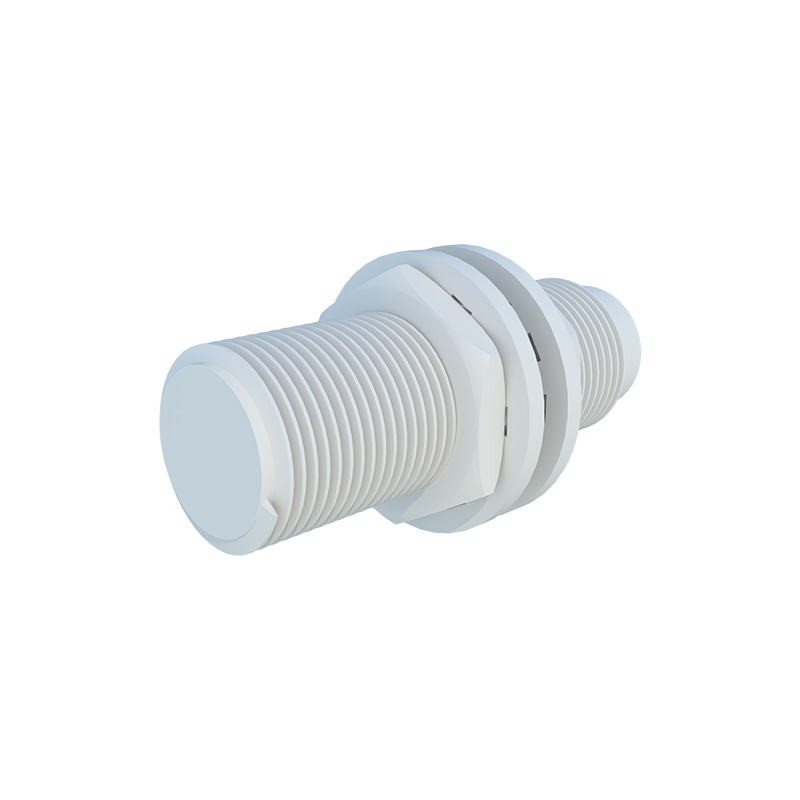
The next critical stage is Housing Manufacturing and Assembly. Metal housings are typically created through CNC machining or precision die-casting to achieve the required tolerances and thread specifications (e.g., M8, M12, M18). Plastic housings are injection-molded from engineering-grade thermoplastics. The internal assembly is a meticulous process. The potted coil assembly and the populated PCB are carefully integrated into the housing. Connections are soldered, and often, the entire internal cavity is filled with a epoxy resin compound. This potting process is vital as it provides mechanical stability, excellent heat dissipation, and complete protection from contaminants like dust, oil, and coolants, ensuring the sensor meets IP67, IP68, or IP69K standards.
Laser Marking and Cabling comes next. The sensor body is permanently marked with its model number, electrical ratings, brand logo, and often a QR code for traceability using laser marking systems. For sensors with integrated cables, the appropriate cable type (PVC, PUR) is stripped, and its wires are connected to the internal terminals. The cable entry point is sealed with a gland or grommet and additional potting to maintain the ingress protection rating. For connector-type variants (e.g., M12 connectors), the mating connector is assembled and secured.
No manufacturing process is complete without rigorous Testing and Calibration, which is arguably the most crucial phase. Every single sensor undergoes a battery of automated tests. Key parameters checked include:
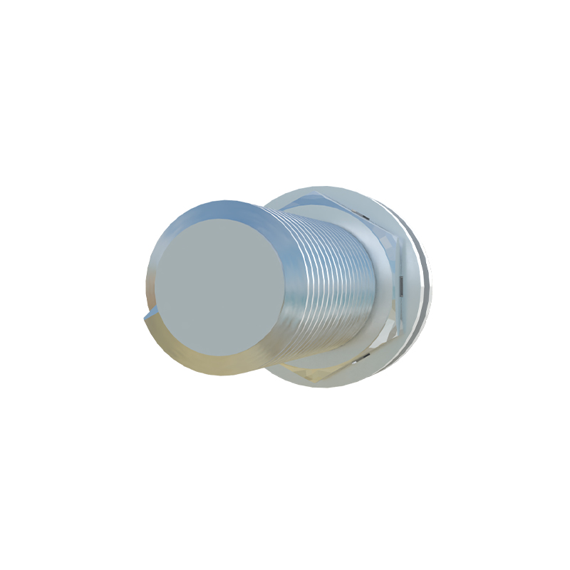
Functionality Test: The sensor is exposed to a target at its specified sensing distance to verify switching action.
Electrical Test: Output current, leakage current, voltage drop, and short-circuit protection are measured.
Hysteresis Test: The difference between the switch-on and switch-off points is verified to ensure stable operation.
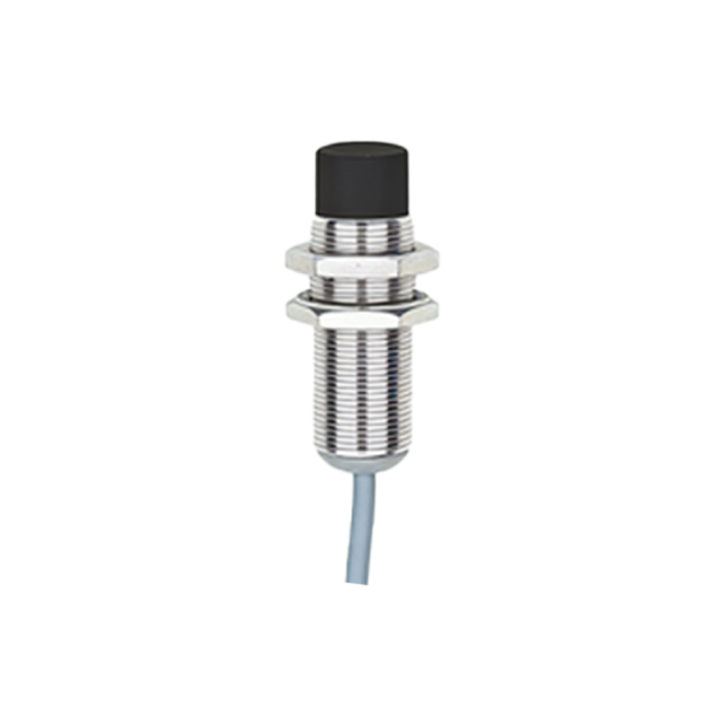
Temperature Cycling: Sensors are subjected to high and low temperatures within their specified range to check for performance drift.
IP Rating Test: A sample from each batch undergoes spray, immersion, or dust tests to validate the sealing integrity.
Calibration equipment adjusts the oscillator circuit if necessary to ensure the sensing distance is within the tight tolerances specified in the datasheet. Only units passing all tests are approved for packaging.
Finally, sensors proceed to Final Packaging and Logistics. They are cleaned, often given a protective coating, and packaged according to customer requirements—in individual boxes, blister packs, or bulk containers. Packaging includes essential documentation like data sheets and certificates of conformity. Modern manufacturing lines integrate sophisticated ERP and MES systems to track every component and every production step, ensuring full traceability from raw material to shipped product.
In conclusion, the manufacturing of proximity sensors is a highly automated and controlled process. It demands precision at every step—from the micron-level accuracy of coil winding and SMT placement to the robust sealing for harsh industrial environments. Understanding this process allows electrical engineers to better select sensors, troubleshoot application issues, and appreciate the engineering marvel embedded in these ubiquitous devices that form the sensory backbone of automated systems worldwide.