In the realm of industrial automation and control systems, proximity sensors stand as fundamental components for non-contact object detection. Among the various output configurations, PNP (Positive-Negative-Positive) sensors are widely prevalent, particularly in European and Asian markets. This article delves into the specifics of PNP proximity sensor models, their operational principles, key specifications, and application considerations, providing a detailed guide for electrical engineers and system designers.
A PNP proximity sensor, in essence, is a solid-state electronic device that detects the presence or absence of a target object without physical contact. The "PNP" designation refers to the type of transistor used in its output switching circuit. In a PNP output configuration, the sensor's output wire (typically the black or brown wire) switches the positive voltage supply to the load. When an object enters the sensor's detection range, the internal PNP transistor saturates, connecting the output terminal to the positive supply voltage (+V). This means the sensor acts as a sourcing device, providing a positive voltage signal to the connected load, such as a PLC (Programmable Logic Controller) input, relay, or indicator lamp.
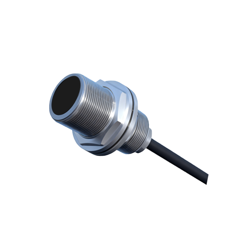
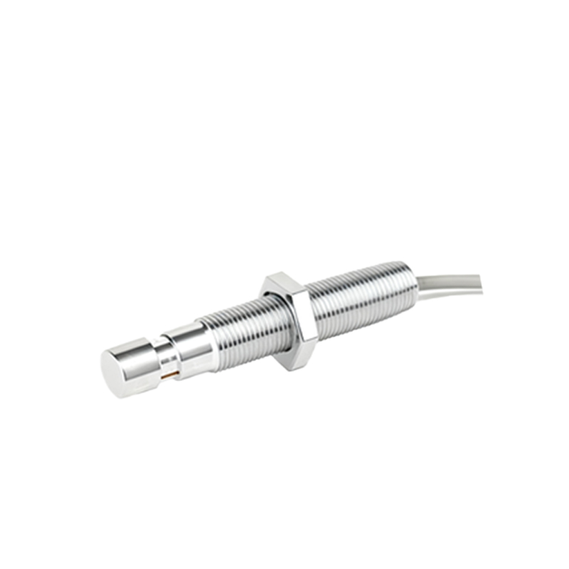
Understanding model numbers is crucial for proper selection. Manufacturers encode critical specifications within the model designation. A typical model number, for instance, might be "E2E-X18MY1" or "PR12-4DN". While formats vary by brand, common embedded parameters include sensing distance (e.g., 2mm, 5mm, 8mm, 12mm), housing shape (cylindrical, rectangular, block-style), sensing face type (shielded or unshielded), connection method (cable or connector), and output function (normally open or normally closed). The sensing distance, a paramount specification, defines the nominal range at which the sensor can reliably detect a standard target. Engineers must carefully match this to the application's mechanical tolerances.
Electrical characteristics form the core of any datasheet. The operating voltage range for DC PNP sensors is commonly between 10-30V DC. The output current rating, often 100mA to 300mA, dictates the maximum load the sensor can drive directly. It is imperative not to exceed this rating to prevent damage. The voltage drop across the sensor's output transistor, known as the saturation voltage (Vce(sat)), is typically below 2V, ensuring sufficient voltage reaches the load. Additionally, the no-load current consumption and short-circuit/overload protection features are vital for system reliability and design of the power supply.
Environmental and performance ratings are equally important. The Ingress Protection (IP) rating, such as IP67 or IP69K, indicates the sensor's resilience against dust and water, determining its suitability for harsh washdown or outdoor environments. Temperature ranges for operation and storage ensure functionality in cold storage or foundry applications. Switching frequency, measured in Hertz (Hz), defines how quickly the sensor can detect objects passing by, a critical factor in high-speed counting or sorting lines. Repeatability, the precision of the detection point, affects positioning accuracy.
Choosing the correct model involves a systematic approach. First, define the target material (usually ferrous or non-ferrous metals). Inductive sensors detect metals, while capacitive models can detect liquids, plastics, or other materials. Second, determine the required sensing distance with a safety margin. Third, select the housing material (e.g., stainless steel, nickel-plated brass, or PBT plastic) based on chemical exposure and mechanical stress. Fourth, verify the electrical compatibility: ensure the PNP sourcing output matches the sinking input of your PLC (common in many PLC designs). Finally, consider special features like weld-field immunity (for robotic welding), analog output for distance measurement, or IO-Link capability for smart sensor diagnostics and parameterization.
Common wiring practices must be adhered to. A standard 3-wire DC PNP sensor has brown (+V), blue (0V/Common), and black (Output) wires. The brown wire connects to the positive DC supply, blue to the negative/ground, and the black output wire connects to the load. The other terminal of the load is then connected to the negative supply. Always refer to the manufacturer's datasheet for the specific pinout. For noise immunity and stable operation, using shielded cables in electrically noisy environments and installing suppression diodes for inductive loads (like relays or solenoids) are recommended best practices.
In troubleshooting, understanding the model's LED indicator behavior is key. A steady or blinking LED often indicates power, target detection, or error states. Common issues include incorrect wiring (e.g., confusing PNP with NPN), insufficient sensing distance, electrical noise interference, or physical damage to the sensing face. Always verify power supply voltage and polarity first.
In conclusion, PNP proximity sensor models encapsulate a wealth of