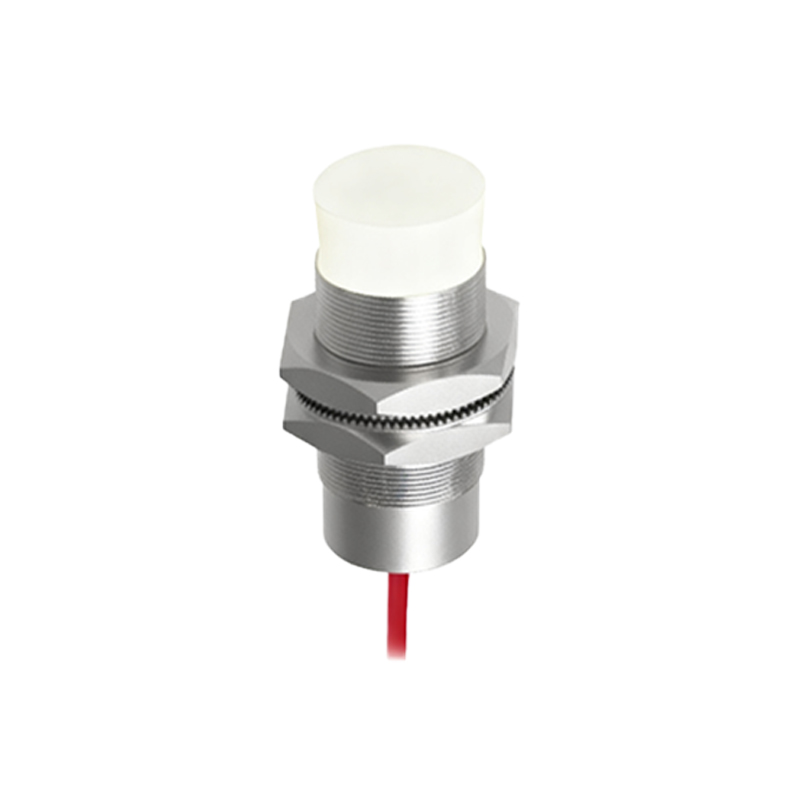
In the realm of industrial automation, robotics, and consumer electronics, infrared (IR) proximity sensors are indispensable components for non-contact detection. Their operation hinges on the principles of infrared light emission and reception, translated into practical circuits through carefully designed schematics. This article delves into the core components and typical circuit configurations of a standard IR proximity sensor, explaining the signal flow and key considerations for implementation.
At its heart, an IR proximity sensor schematic consists of two primary sections: the transmitter and the receiver. The transmitter circuit is responsible for generating a modulated infrared signal. This typically involves an oscillator circuit—often built around a 555 timer IC or a microcontroller's PWM pin—driving an infrared Light Emitting Diode (IR LED). The modulation, usually at a frequency between 30-40 kHz, is crucial. It allows the receiver to distinguish the sensor's own emitted light from ambient infrared radiation (e.g., from sunlight or indoor lighting), dramatically improving noise immunity and reliability. A current-limiting resistor is always placed in series with the IR LED to prevent its burnout.
The receiver section is more complex. Its central component is an infrared photodiode or, more commonly, a dedicated IR receiver module. A simple photodiode circuit will change its conductivity proportionally to the amount of IR light incident upon it. However, a standalone photodiode is susceptible to ambient light interference. Therefore, most practical schematics incorporate a pre-packaged IR receiver module (like the ubiquitous VS1838B or TSOP series). These modules integrate a photodiode, a preamplifier, a band-pass filter tuned to the modulation frequency (e.g., 38 kHz), and a demodulator circuit into a single three-pin device (Vcc, GND, Output). This integration simplifies design and provides a clean, digital output signal—low when the modulated IR signal is detected, and high when it is absent.
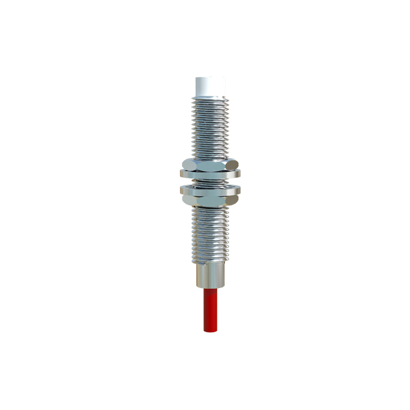
The classic reflective proximity sensor schematic connects these two sections. The modulated IR light from the transmitter LED is emitted towards a target. If an object is within the detection range, a fraction of this light is reflected back towards the IR receiver module. The module, tuned to the correct frequency, detects this reflected signal and its output pin toggles state. This digital output can then be fed directly into a microcontroller's GPIO pin for further processing. The detection range is influenced by the IR LED's output power, the receiver's sensitivity, and the reflectivity of the target object. Resistors and capacitors are strategically placed around both the oscillator and the receiver module for stable operation, following the manufacturer's datasheet recommendations.
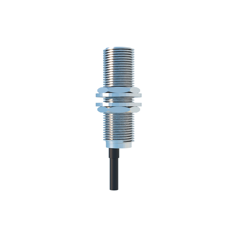
For more precise distance measurement or to detect specific materials, variations exist. Some advanced schematics use a pair of closely matched photodiodes in a differential configuration to cancel out common-mode ambient noise. Others might employ a time-of-flight (ToF) principle, requiring a much faster circuit with a high-speed emitter and a precision timer to measure the round-trip time of an infrared pulse.
When interpreting or designing an IR proximity sensor schematic, several critical factors must be considered. Power supply decoupling is essential; a 0.1µF ceramic capacitor should be placed close to the Vcc pins of both the oscillator IC and the receiver module to filter high-frequency noise. The physical layout is equally important; the IR LED and the receiver must be positioned to minimize direct crosstalk (light leaking directly from LED to receiver without reflection) while optimizing the field of view for the target area. Optical barriers or tubes are often used in the mechanical design to achieve this. Furthermore, the choice of modulation frequency and the receiver's matching filter bandwidth will determine the sensor's immunity to interference from other IR sources, such as remote controls.
In summary, the schematic of an infrared proximity sensor elegantly translates an optical principle into a robust electronic system. By understanding the distinct roles of the transmitter oscillator, the IR LED, the integrated receiver module, and the supporting passive components, engineers can effectively deploy, troubleshoot, or customize these sensors for a vast array of applications, from simple object detection to complex ambient light rejection and distance sensing tasks. Always cross-reference the specific component datasheets for optimal resistor and capacitor values in your final design.