In industrial automation and machinery design, proximity sensors play a critical role in detecting the presence or absence of objects without physical contact. Among the various types, inductive and capacitive proximity sensors are widely used for their reliability and durability in harsh environments. One common yet often overlooked aspect of their installation and maintenance is the adjustment of sensing distance, particularly through clockwise rotation of adjustment mechanisms. This article delves into the technical nuances of clockwise adjustment for proximity sensors, offering insights into best practices, common pitfalls, and industry-standard procedures.
Proximity sensors typically feature a built-in potentiometer or a mechanical adjustment screw that allows fine-tuning of the sensing range. Clockwise rotation of this adjustment component generally increases the sensing distance, enabling the sensor to detect objects from a farther range. This adjustment is essential for optimizing performance in applications where precise positioning is required, such as in conveyor systems, robotic arms, or assembly lines. Engineers must understand the sensor's datasheet specifications, including the maximum sensing distance and hysteresis, to avoid over-adjustment that could lead to false triggers or reduced sensitivity.
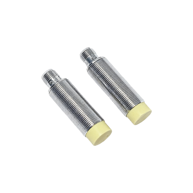
The process begins with ensuring the sensor is properly installed and powered according to manufacturer guidelines. Using a non-metallic adjustment tool, engineers should rotate the adjustment screw clockwise in small increments—typically 5 to 10 degrees at a time—while monitoring the sensor's output signal with a multimeter or oscilloscope. It is crucial to test the adjustment with a target object at the desired distance to verify responsiveness. In environments with electromagnetic interference or temperature fluctuations, additional calibration may be necessary, as these factors can affect sensor performance.
Common mistakes during clockwise adjustment include excessive rotation, which can push the sensor beyond its operational limits, causing permanent damage or erratic behavior. Another issue is neglecting to account for the sensor's hysteresis, the difference between the switch-on and switch-off points. Over-adjustment might narrow this gap, leading to unstable detection. Engineers should also consider the target material; for inductive sensors, metallic objects require different settings compared to non-metallic ones, and clockwise adjustment may not linearly correlate with distance for all materials.
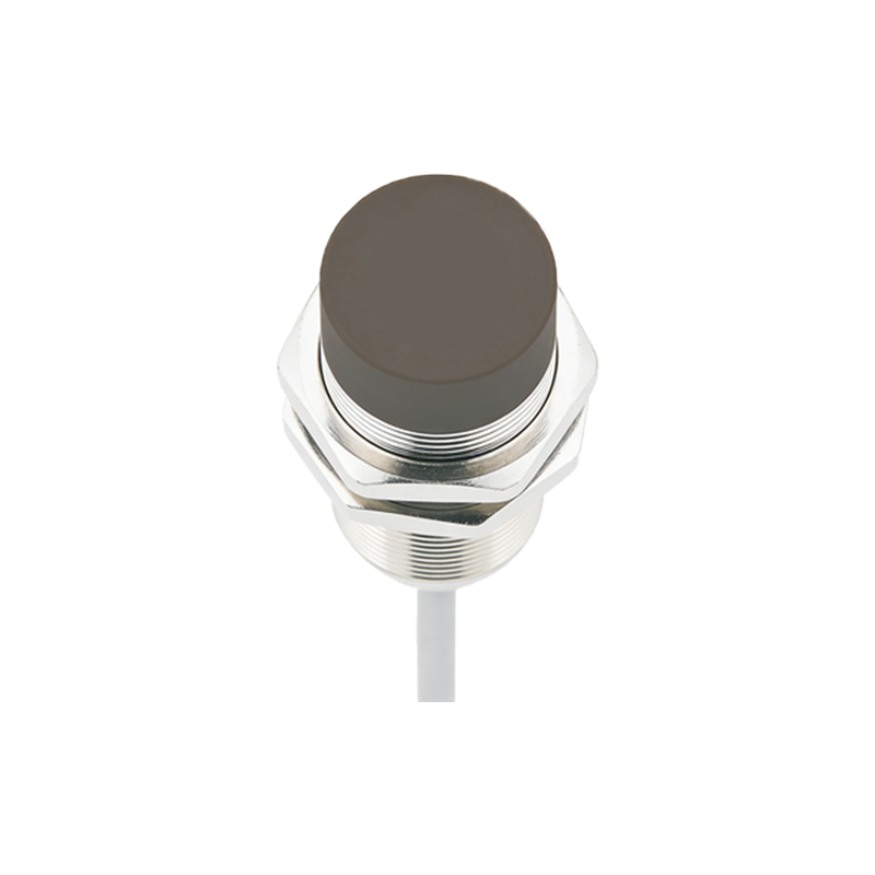
Industry standards, such as those from IEC 60947-5-2, provide guidelines for proximity sensor installation and adjustment. Regular maintenance, including periodic recalibration through clockwise or counterclockwise adjustments, ensures long-term reliability. In safety-critical applications, like those in automotive or aerospace industries, documented adjustment logs and validation tests are mandatory to comply with quality assurance protocols.
Advanced proximity sensors now incorporate digital interfaces, allowing for programmable adjustment via software. However, the fundamental principle of clockwise mechanical adjustment remains relevant for many legacy systems and field applications. Training for technicians should emphasize hands-on practice with adjustment techniques, coupled with theoretical knowledge of sensor physics.
In summary, clockwise adjustment of proximity sensors is a precise task that demands attention to detail and adherence to technical specifications. By following systematic procedures and avoiding common errors, engineers can optimize sensing distances, enhance system efficiency, and reduce downtime. As automation evolves, mastering these foundational skills continues to be vital for maintaining robust industrial operations.