In the demanding world of industrial automation, proximity sensors are the silent sentinels, providing critical non-contact detection for position, presence, and motion. Their reliability is paramount, but this reliability is inextricably linked to a component often overlooked: the cable. When these sensors are mounted on moving machine parts, such as robotic arms, CNC tool changers, or automated gantries, their connecting cables are subjected to continuous flexing, torsion, and mechanical stress within cable carriers (often called drag chains or energy chains). Selecting and installing the wrong cable in this dynamic environment is a recipe for premature failure, costly downtime, and compromised safety. This article delves into the specific requirements for proximity sensor cables designed for use in cable carriers, outlining key selection criteria, installation best practices, and common pitfalls to avoid.
Not all cables are created equal. A standard, fixed-installation cable will rapidly degrade when subjected to the repetitive bending cycles inside a cable carrier. Cables designed for dynamic applications, particularly those for sensitive analog or digital signals from proximity sensors, are engineered from the inside out to withstand these conditions. The core construction begins with finely stranded, high-flex copper conductors. These strands allow the conductor to bend more easily without work-hardening and breaking. The insulation material is equally critical; it must be flexible, durable, and resistant to oils, coolants, and other common industrial contaminants. Materials like thermoplastic elastomers (TPE) or specially formulated polyurethanes (PUR) are common choices, offering an excellent balance of flexibility and toughness.
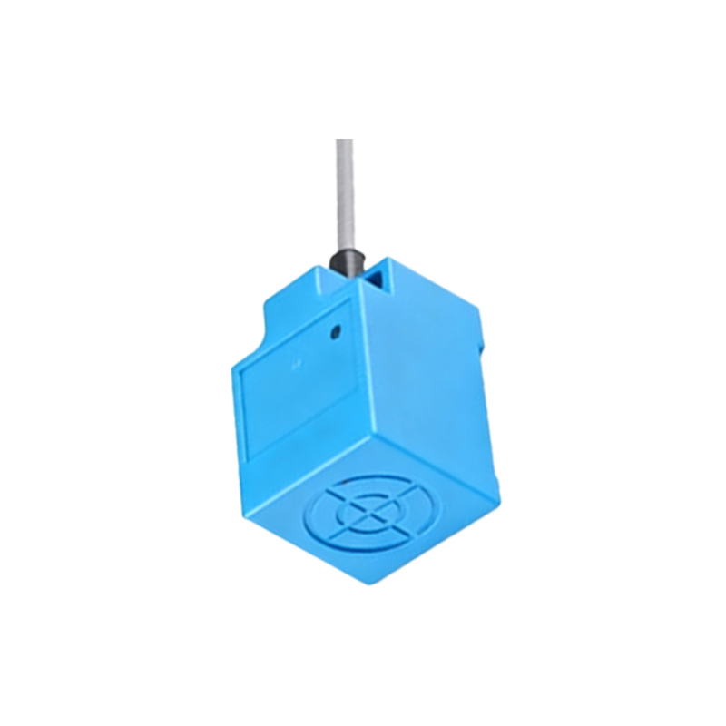
The cable's internal layout is strategically designed to minimize internal stress. Conductors are often arranged in a tension-optimized, layered or bundled core construction. A key feature is the inclusion of dedicated center strain relief elements, such as aramid yarns (e.g., Kevlar) or fiberglass rods. These non-metallic elements absorb the tensile and torsional forces that would otherwise be transferred directly to the delicate copper conductors. The overall jacket must be robust yet supple, with a smooth, low-friction surface to prevent sticking and abrasion against the carrier's dividers and other cables. For sensors in hygienic or washdown environments, a jacket with resistance to cleaning agents is essential.
Selecting the right cable involves matching its specifications to the application's parameters. The most vital specification is the minimum bending radius, both for the cable itself and as prescribed by the cable carrier manufacturer. Exceeding this radius drastically shortens cable life. The required flex life, often rated in millions of cycles, must be evaluated against the machine's operational cycles. Environmental factors cannot be ignored: temperature range, exposure to UV light, oils, acids, or alkalis will dictate the necessary material compounds. Furthermore, the electrical requirements of the proximity sensor—whether it's a simple 2-wire AC/DC model, a 3-wire DC sensor, or a more complex analog or IO-Link device—determine the necessary number of cores, shielding, and conductor gauge. Shielded cables are typically recommended to protect the sensor's signal from electromagnetic interference (EMI) prevalent in industrial settings, especially when running alongside motor power cables in the same carrier.
Even the best cable will fail if installed incorrectly. Proper installation within the cable carrier is a discipline in itself. The cable must never be pulled taut; a slight sag should be allowed to permit movement without placing the conductors under constant tension. It is crucial to follow the carrier manufacturer's guidelines for fill capacity—overfilling a carrier generates heat and increases internal abrasion. Cables should be laid side-by-side and never stacked on top of one another unless the carrier is specifically designed for it. Secure, but not overtightened, cable clamps at both the moving and fixed ends are mandatory to provide strain relief and prevent pull-out forces from reaching the sensor's connection point. The cable's natural twist should be allowed to relax before securing it; forcing it into position creates internal stress. Finally, the cable's entry and exit points from the carrier must be smooth, using appropriate radius guides or rollers to prevent sharp bending or pinching.
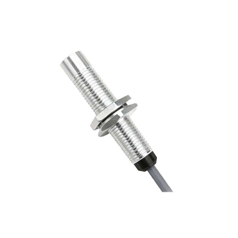
Common failure modes for improperly specified or installed sensor cables in carriers include conductor breakage (often at the point of termination), insulation cracking or peeling, and shield degradation leading to signal noise or loss. Proactive maintenance involves regular visual inspections for signs of jacket wear, cracking, or deformation. Monitoring for intermittent sensor operation can be an early indicator of cable fatigue.
In conclusion, the cable connecting a proximity sensor in a dynamic cable carrier application is a critical wear component. Treating it as an afterthought risks the entire sensing system's integrity. By investing in high-flex, carrier-rated cables engineered for the specific environment and adhering to rigorous installation protocols, engineers and maintenance personnel can ensure maximum sensor performance, reduce unplanned downtime,