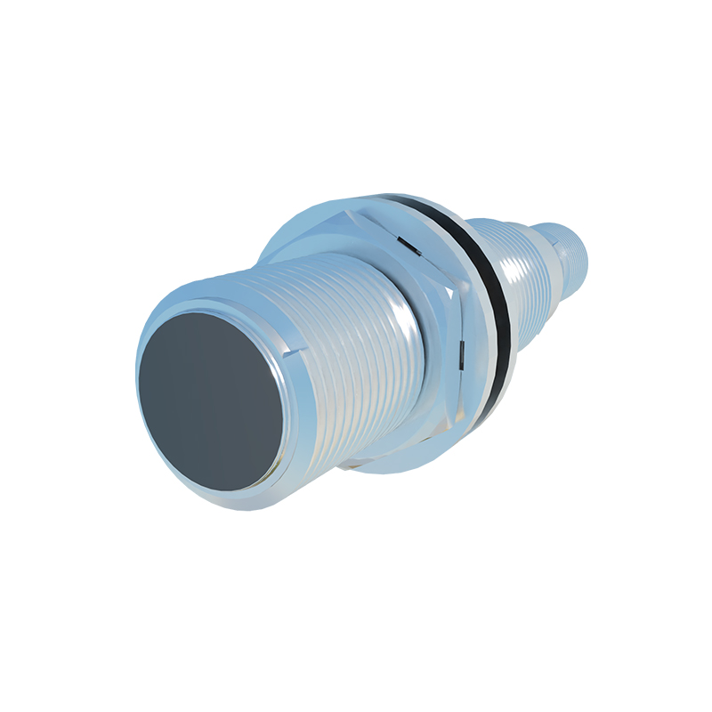
Proximity sensors are essential components in modern industrial automation, enabling non-contact detection of objects within a specific range. These sensors operate based on various physical principles, each suited to different applications and environments. This article delves into the working principles of common proximity sensor types, supported by schematic diagrams to illustrate their internal mechanisms and signal processing pathways.
Inductive proximity sensors are widely used for detecting metallic objects. The core of an inductive sensor consists of a coil wound around a ferrite core, an oscillator, a demodulator, and an output circuit. When an AC voltage is applied, the oscillator generates a high-frequency electromagnetic field around the active face of the sensor. As a metallic object enters this field, eddy currents are induced on the object's surface, causing a change in the oscillation amplitude. The demodulator converts this change into a DC signal, which triggers the output circuit (typically a transistor) to switch states. A schematic diagram would show the oscillator connected to the coil, with feedback loops to the demodulator, leading to the output stage. This design allows for reliable detection without physical contact, making it ideal for harsh industrial environments.
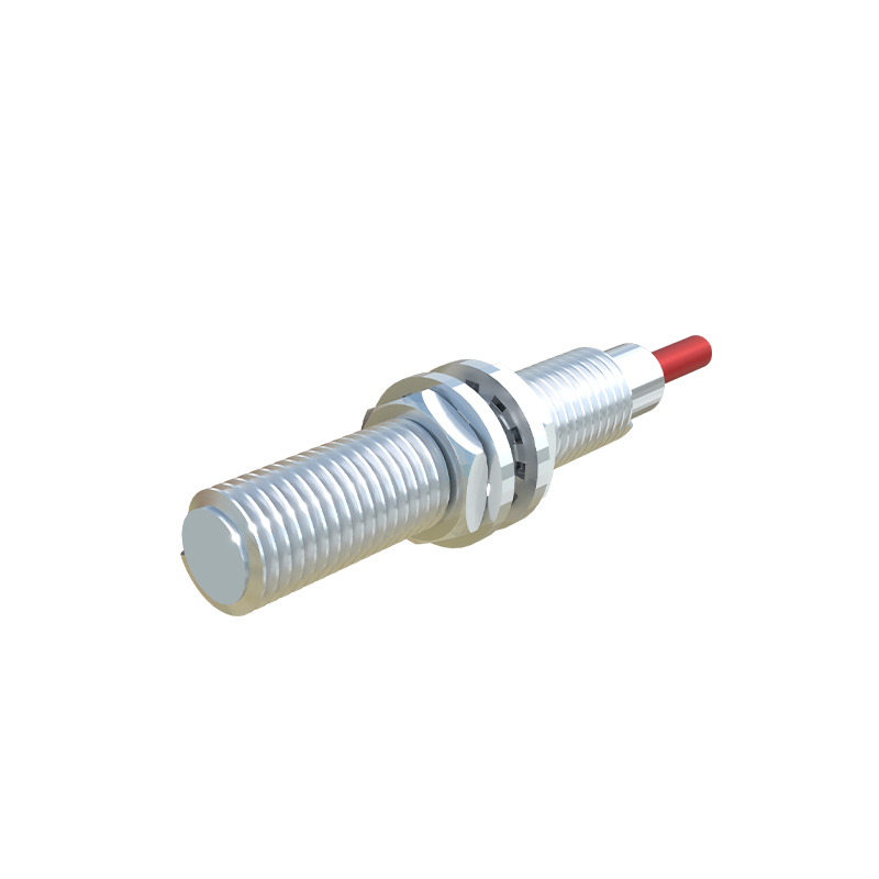
Capacitive proximity sensors can detect both metallic and non-metallic materials, including liquids and powders. These sensors utilize a capacitor formed by two electrodes: one as the active electrode (sensing face) and the other as the ground electrode. An oscillator circuit charges the capacitor, creating an electrostatic field. When an object enters the field, the capacitance changes, altering the oscillation amplitude. This change is processed by a threshold circuit to activate the output. A schematic diagram typically depicts the oscillator linked to the electrode plates, with a comparator circuit monitoring capacitance shifts. The ability to sense through non-conductive materials makes capacitive sensors versatile for packaging, level detection, and material handling applications.
Ultrasonic proximity sensors employ sound waves for detection. They contain a transmitter that emits high-frequency ultrasonic pulses and a receiver that captures reflected echoes. The time delay between emission and reception is measured to calculate the distance to an object. A schematic diagram illustrates the transmitter and receiver transducers connected to a control unit, which processes the signal using a time-to-digital converter. These sensors are effective for long-range detection and are commonly used in robotics, vehicle parking systems, and liquid level monitoring.
Photoelectric proximity sensors use light beams to detect objects. They consist of a light emitter (usually an LED or laser diode) and a photodetector (such as a phototransistor). When an object interrupts or reflects the light beam, the photodetector registers a change in light intensity, triggering the output. Schematics show the emitter driven by a current source and the detector connected to an amplifier and comparator circuit. Variants include through-beam, retro-reflective, and diffuse reflection models, each with distinct wiring and component layouts. Photoelectric sensors offer high precision and are prevalent in conveyor systems, safety barriers, and counting applications.
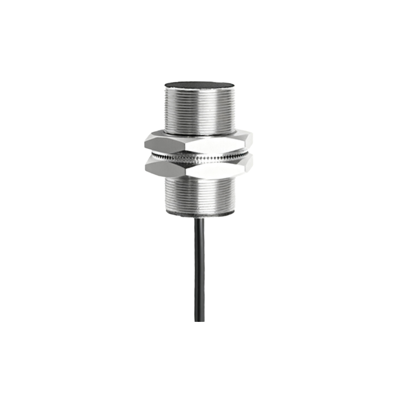
Hall effect proximity sensors detect magnetic fields and are used for sensing permanent magnets or ferrous materials. They incorporate a Hall element that generates a voltage proportional to the magnetic field strength. When a magnet approaches, the Hall voltage changes, activating a Schmitt trigger or amplifier circuit to produce an output signal. A schematic diagram highlights the Hall element connected to signal conditioning circuitry, ensuring stable operation despite temperature variations. These sensors are integral to position sensing in automotive and brushless DC motor applications.
In summary, proximity sensors leverage electromagnetic, capacitive, ultrasonic, optical, or magnetic principles to enable efficient object detection. Schematic diagrams provide clarity on their internal design, showcasing components like oscillators, demodulators, transducers, and output stages. Understanding these principles aids in selecting the right sensor for specific industrial needs, enhancing automation reliability and performance.