In industrial automation and control systems, proximity sensors are indispensable components for non-contact detection of objects. A common and critical issue encountered by maintenance engineers and system integrators is a sensor registering a voltage output of 0 volts (V) when it should be active. This condition, often indicated on a PLC input module or a multimeter reading, signifies a failure in the signal chain. Diagnosing this fault requires a systematic approach grounded in an understanding of sensor operation, wiring configurations, and external influences.
Firstly, it is crucial to distinguish between the power supply voltage and the output signal voltage. A proximity sensor requires a DC supply voltage, typically 10-30V DC, to operate its internal oscillator and switching circuit. The output voltage is the signal presented on the output wire (usually black or blue) relative to the common (0V) wire. A reading of 0V at the output can mean either a true "OFF" state or a fault condition.
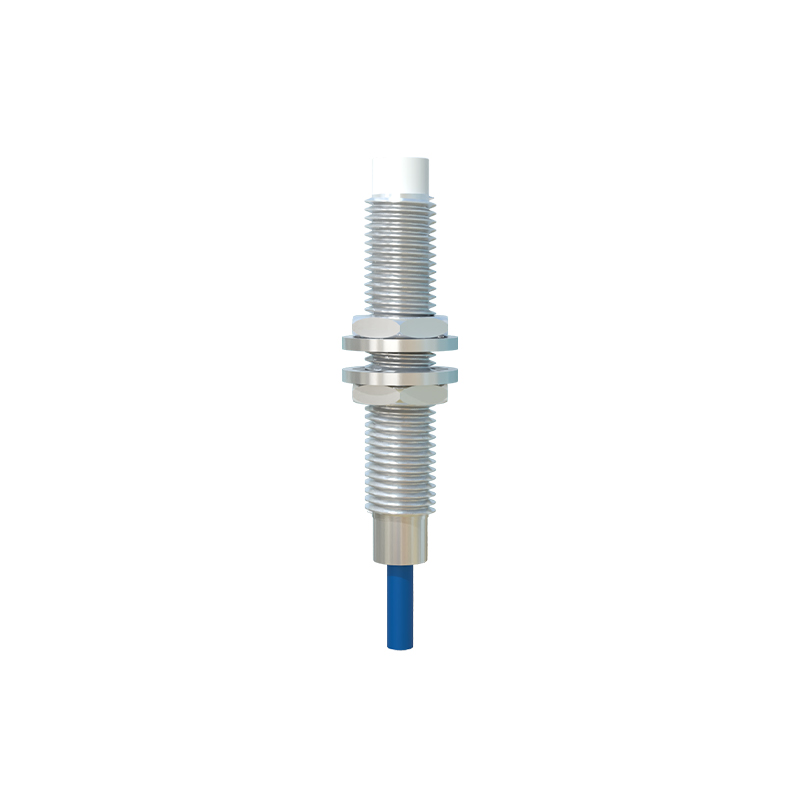
The most fundamental step is to verify the power supply. Use a digital multimeter to measure the voltage between the sensor's positive (brown, typically) and negative (blue) supply terminals. A reading of 0V or significantly below the rated voltage (e.g., below 10V for a 12-24V DC sensor) indicates a power issue. Check the circuit breaker, fuse, power supply unit, and all wiring connections for breaks, looseness, or corrosion. Remember, without proper supply voltage, the sensor cannot generate an output signal.
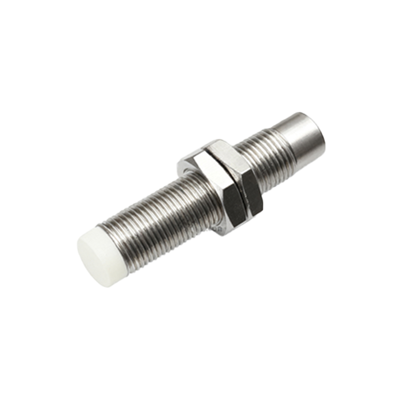
Assuming the supply voltage is correct, the next step is to understand the sensor's output type. The two primary types are NPN (sinking) and PNP (sourcing). An NPN sensor switches the output to the common (0V) line when active, meaning the signal wire itself goes to near 0V. A PNP sensor switches the output to the positive supply voltage when active. Confusion arises when interfacing with a PLC. If a PNP sensor is incorrectly connected to an NPN-input PLC card (or vice-versa), the PLC may read a constant 0V. Always verify the sensor datasheet and the PLC input module specifications for compatibility (sourcing vs. sinking).
Wiring errors are a frequent culprit. A loose connection on the output wire, a severed cable, or a faulty connector can result in an open circuit, presenting 0V at the measurement point. For 3-wire sensors, ensure the brown (+V), blue (0V/common), and black (output) wires are connected correctly. For 4-wire sensors (with two outputs), verify the wiring diagram. Also, check for short circuits. If the output wire is accidentally shorted to the 0V (blue) wire, the output will be pulled to 0V permanently, regardless of the sensor's state. Inspect the cable along its entire run for pinch points, abrasion, or damage.
The sensor's sensing face and target must be evaluated. Dirt, metal chips, grease, or other contaminants on the sensing face can attenuate or block the electromagnetic field (for inductive sensors) or the infrared beam (for capacitive or optical types), preventing the sensor from activating. Ensure the target is within the specified sensing distance (Sn) and is of the correct material and size. An inductive sensor will not detect non-metallic objects. The target should approach the sensor axially, not radially, for optimal performance.
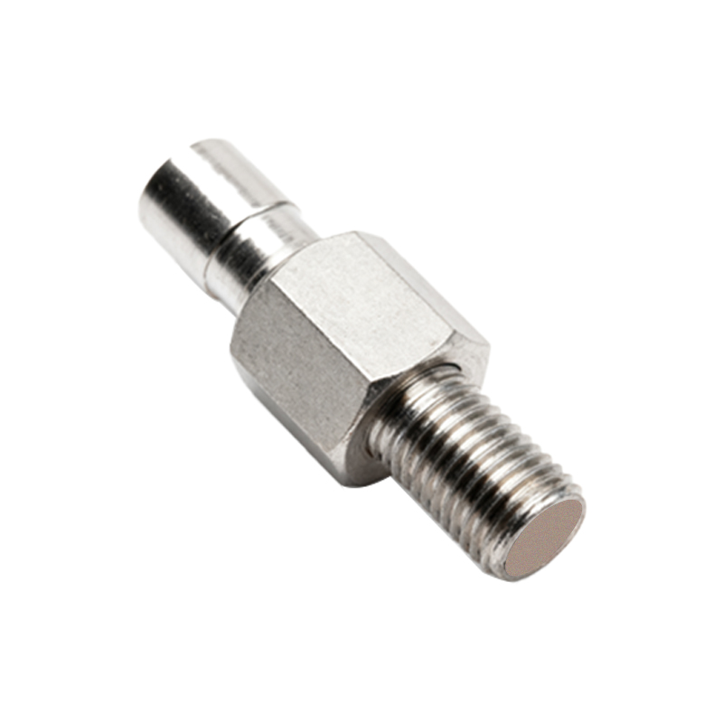
Internal sensor failure, though less common than wiring issues, can occur. Overvoltage transients, excessive current load, physical damage, or prolonged exposure to harsh environments (extreme temperatures, chemicals) can damage the output switching transistor or integrated circuit. If all external factors—power, wiring, wiring compatibility, and target—have been ruled out, the sensor itself may be faulty. Substituting with a known-good sensor of the same type is a definitive test.
Electrical noise and load compatibility are advanced considerations. Severe electromagnetic interference (EMI) from nearby motors, variable frequency drives (VFDs), or welding equipment can disrupt the sensor's internal electronics, potentially causing erratic behavior or a locked 0V output. Ensure proper shielding, grounding, and separation of signal cables from power lines. Additionally, check if the load connected to the sensor (e.g., PLC input, relay coil) is within the sensor's maximum current rating. An overloaded output can fail in a short-circuit state.
A structured troubleshooting flowchart is highly effective:
1. Measure supply voltage at sensor terminals. If 0V, troubleshoot power circuit.
2. Verify correct output type (PNP/NPN) matches the load/PLC input.
3. Inspect all wiring and connections for opens, shorts, and correctness.
4. Clean the sensing face and verify target presence, material, and distance.