In automated industrial systems, proximity sensors are indispensable for non-contact detection of objects, ensuring precise positioning, counting, and safety functions. However, a common and often perplexing issue arises when two or more proximity sensors are installed in close proximity: mutual interference or crosstalk. This conflict can lead to erratic behavior, false triggering, or complete failure of the sensing system, jeopardizing process reliability and safety. This article delves into the root causes of such interference between two proximity sensors and provides practical engineering solutions.
The primary cause of conflict between two inductive or capacitive proximity sensors is electromagnetic field interaction. Each sensor generates its own oscillating electromagnetic field. When placed too close, the field from one sensor (the "aggressor") can influence the oscillator circuit of the adjacent sensor (the "victim"). This can cause the victim sensor to interpret the external field as a change in its own sensing field, leading to an unstable output even when no target is present. For photoelectric sensors, optical crosstalk can occur if the light beam from one sensor is reflected into the receiver of another.
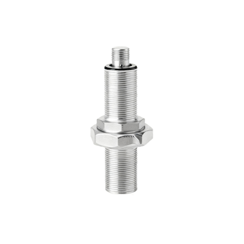
Several key factors determine the severity of this interference:
1. Sensor Type: Inductive sensors are most susceptible to mutual interference due to their electromagnetic fields. Capacitive sensors can also interfere, especially in the presence of the same dielectric material. Photoelectric sensors face optical rather than electromagnetic issues.
2. Operating Frequency: Many modern sensors offer selectable switching frequencies (e.g., 5 kHz, 500 Hz, 100 Hz). Sensors set to the same or harmonically related frequencies are far more likely to interfere.
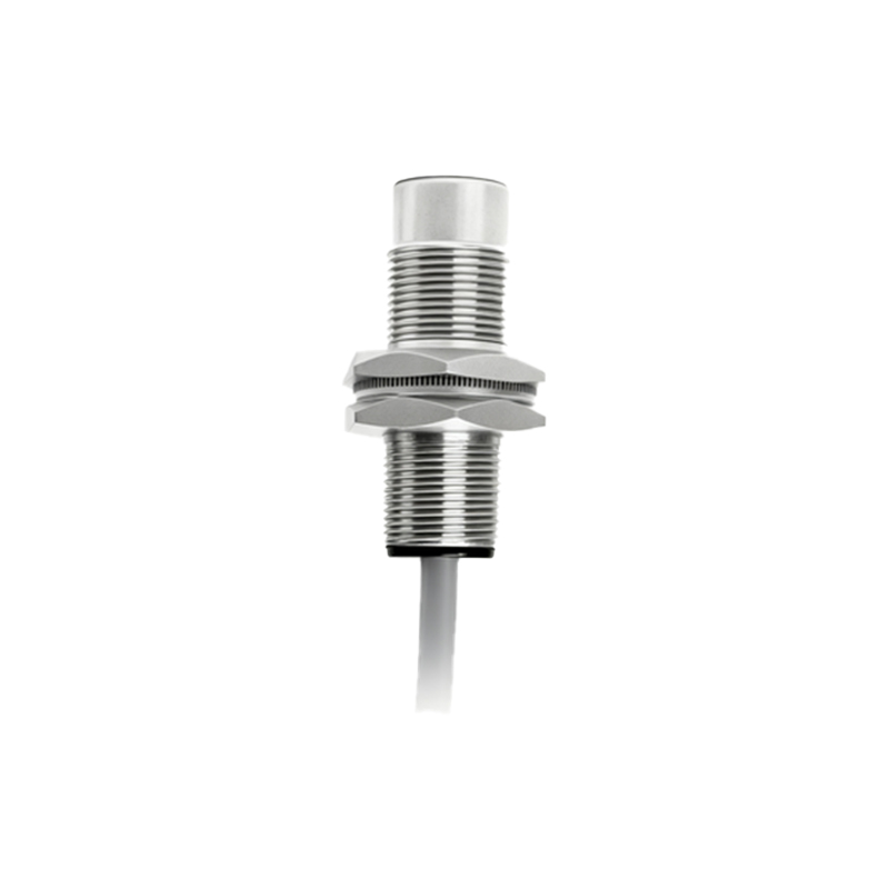
3. Physical Distance and Orientation: The closer the sensors, the stronger the potential interference. Parallel mounting of cylindrical sensors side-by-side is a typical problematic configuration. The relative orientation of the sensing faces significantly impacts field overlap.
4. Shielding: Shielded (flush-mountable) inductive sensors have a more focused magnetic field along the front axis, while unshielded (non-flush) sensors have a larger, more lateral field. Unshielded sensors are more prone to causing and experiencing interference.
5. Power Supply and Wiring: Shared power supplies with inadequate filtering or parallel wiring runs can introduce electrical noise, compounding the interference problem.
To systematically resolve conflicts between two proximity sensors, follow this engineering approach:
1. Increase Physical Separation: This is the most straightforward method. Consult the sensor's datasheet for the recommended minimum separation distance. For unshielded inductive sensors, this distance can be 3-4 times the sensor's rated sensing distance. For shielded types, 1-2 times may suffice. Increasing the axial offset or mounting sensors at 90 degrees to each other can dramatically reduce field overlap.
2. Utilize Different Operating Frequencies: If your sensor models allow frequency selection, configure adjacent sensors to operate on different frequencies. For instance, set one sensor to a high frequency (e.g., 5 kHz) and its neighbor to a low frequency (e.g., 100 Hz). This prevents their oscillators from synchronizing or influencing each other. This is often the most effective solution without requiring mechanical redesign.
3. Select the Appropriate Sensor Type: Opt for shielded (flush-mountable) inductive sensors in dense installations. Their confined field minimizes lateral interaction. In extremely tight spaces, consider using a different sensing principle altogether. Fiber-optic photoelectric sensors paired with a single, remotely mounted amplifier are highly immune to electromagnetic crosstalk and are ideal for clustered sensing points.
4. Implement Time-Division Multiplexing (Synchronization): Some advanced sensor families offer a synchronization function (often called "Sync" or "Crosstalk Immunity" mode). This requires a dedicated synchronization wire between the sensors. In this mode, the sensors are powered and activate their fields in a precisely timed, alternating sequence, ensuring they are never active simultaneously. This virtually eliminates mutual interference even at very close distances.
5. Optimize Electrical Installation: Use separate, shielded cables for each sensor. Ground the shield properly at the controller end. Ensure a stable, clean power supply. Consider using individual power supplies or power supply modules with high noise immunity for critical sensor clusters. Keep sensor cables away from power lines, motor drives, and other sources of electromagnetic noise.
6. Adjust Sensing Parameters: If available, slightly reduce the sensitivity or hysteresis setting of the affected sensor. This can make it less susceptible to the weak external field from its neighbor, though it may also marginally reduce its effective sensing range.
In practice, a combination of these strategies is often employed. For a new panel or machine design, always plan sensor placement considering interference from the outset. For troubleshooting an existing interference issue, start by checking and increasing separation if possible, then investigate frequency settings and the potential for synchronization.
Proactive mitigation of proximity sensor interference is a