Proximity sensors are indispensable components in modern industrial automation, playing a critical role in object detection, positioning, and process control without physical contact. Their correct installation and wiring are paramount for ensuring system reliability, safety, and optimal performance. This guide provides a detailed, step-by-step explanation of standard proximity sensor wiring methods, catering to the needs of electrical engineers and technicians.
Understanding Sensor Types and Outputs
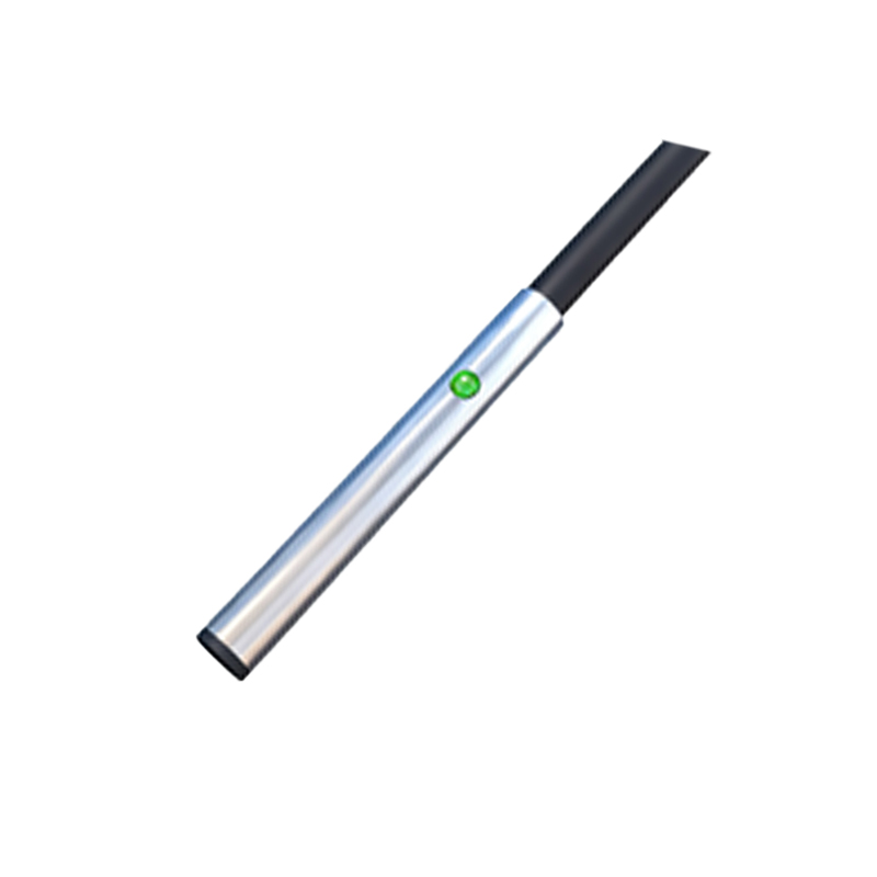
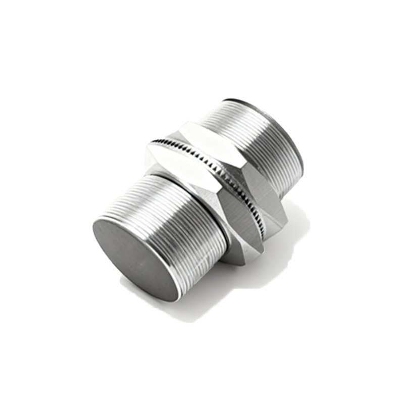
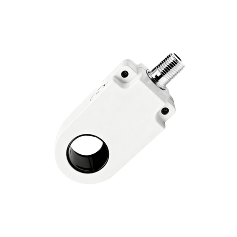
Before diving into wiring, it's crucial to identify the sensor type and its output configuration. The two primary categories are based on the detection principle: Inductive (for metallic objects) and Capacitive (for both metallic and non-metallic objects). More importantly, from a wiring perspective, sensors are classified by their output circuitry:
1. PNP (Sourcing): The output switch connects the load to the positive supply voltage (+V). When activated, it "sources" current to the load.
2. NPN (Sinking): The output switch connects the load to the negative supply voltage (0V or common). When activated, it "sinks" current from the load.
3. Analog Output: Provides a continuous voltage or current signal proportional to the distance to the target.
4. IO-Link: A digital, point-to-point serial communication connection for smart sensors.
Additionally, sensors come with 2-wire, 3-wire, or 4-wire configurations. 3-wire sensors (with separate power, ground, and signal wires) are the most common for DC models and will be the focus of our wiring details.
Standard 3-Wire DC Sensor Wiring
A 3-wire DC proximity sensor typically has three distinct leads, often color-coded as Brown, Blue, and Black (following common international standards, though always verify the datasheet).
Brown Wire: This is the positive supply lead (+V). It must be connected to the positive terminal of the DC power source. The voltage range (e.g., 10-30V DC) is specified in the sensor's manual.
Blue Wire: This is the negative or common (0V) lead. It must be connected to the negative terminal of the DC power source and the common point of the load/controller.
Black Wire: This is the output signal lead. Its function depends on whether the sensor is PNP or NPN.
Wiring a PNP (Sourcing) Sensor:
1. Connect the Brown wire to the DC power supply positive (+V).
2. Connect the Blue wire to the DC power supply negative (0V) and to one terminal of the load (e.g., a PLC input, relay coil, or indicator lamp).
3. Connect the Black (output) wire to the other terminal of the load.
When a target is detected, the PNP sensor's internal switch closes between the Brown and Black wires. It sources current from +V, through the sensor, out the Black wire, through the load, and back to the power supply's 0V via the Blue wire connection at the load.
Wiring an NPN (Sinking) Sensor:
1. Connect the Brown wire to the DC power supply positive (+V).
2. Connect the Blue wire to the DC power supply negative (0V).
3. Connect the Black (output) wire to one terminal of the load.
4. Connect the other terminal of the load to the DC power supply positive (+V).
When a target is detected, the NPN sensor's internal switch closes between the Black and Blue wires. It sinks current from the load, which is connected to +V. Current flows from +V, through the load, into the Black wire, through the sensor, and out the Blue wire to 0V.
Critical Considerations for Reliable Operation
Power Supply: Use a regulated, stable DC power supply within the sensor's specified range. Ripple and noise can cause erratic operation.
Load Compatibility: Ensure the load (PLC input module, relay, etc.) is compatible with the sensor's output type (PNP vs. NPN). Mismatching can lead to malfunction or damage. Many PLC input modules are configurable or have specifications for sourcing/sinking.
Shielding and Cable Routing: In electrically noisy environments (near VFDs, large motors, welding equipment), use shielded cables. Connect the cable shield to a proper earth ground at the controller end only. Route sensor cables separately from power cables to minimize inductive coupling.
Short-Circuit and Overload Protection: While many sensors have built-in short-circuit protection, it is good practice to install an inline fast-acting fuse (typically 100-200mA) on the Brown