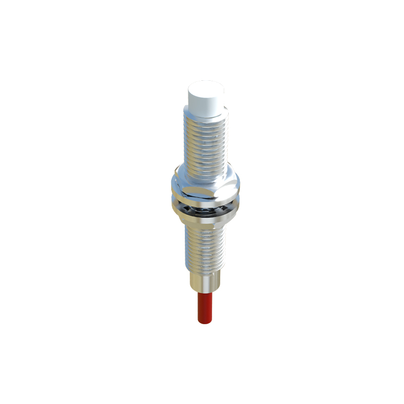
In industrial automation systems, the reliable operation of proximity sensors is paramount for process control, safety interlocks, and positional feedback. A common yet critical issue encountered on the factory floor is when a Programmable Logic Controller (PLC) input module consistently fails to detect the signal from an inductive or capacitive proximity sensor. This failure manifests as a "0" or FALSE state in the PLC logic despite the sensor's perceived operation, leading to machine stoppages, faulty sequencing, or safety hazards. Diagnosing this problem requires a systematic, step-by-step approach grounded in electrical fundamentals.
The first and most crucial phase is verification and observation. Before delving into complex diagnostics, confirm the basic parameters. Check the sensor's part number against the datasheet to verify its operating voltage (commonly 10-30V DC or 90-250V AC), output type (Normally Open/NO, Normally Closed/NC, or NAMUR), and sensing distance. A mismatch between the sensor's supply voltage and the PLC input circuit's sourcing/sinking configuration is a primary culprit. Simultaneously, observe the sensor's indicator LED (if present). A steadily lit or blinking LED typically indicates power and detection, while an unlit LED suggests a power or internal fault. However, note that some two-wire DC sensors may illuminate their LED even with a faulty output stage, making this a preliminary check only.
With basics confirmed, proceed to electrical measurement using a digital multimeter (DMM). Begin at the power source. Measure the voltage between the sensor's supply terminals (+V and -V or Common) under load. A voltage sag below the sensor's minimum operating specification under load indicates an inadequate power supply or excessive current draw. Next, measure the sensor's output signal directly at its wires, disconnected from the PLC if necessary. For a three-wire DC sensor, with the target present, the voltage between the output wire and common should be close to the supply voltage (for a PNP/sourcing sensor) or near 0V (for an NPN/sinking sensor). An unexpected value points to a sensor failure.
The interface between the sensor and the PLC input module demands meticulous scrutiny. Ensure the wiring is correct and secure. A loose connection in the terminal block or a damaged wire can cause intermittent or total failure. Crucially, understand the PLC input circuit's type. A sinking input module requires a sourcing (PNP) sensor output, while a sourcing input module requires a sinking (NPN) sensor output. Connecting a PNP sensor to a sinking input, or vice versa, will not work. Additionally, verify the input module's specifications. Some high-density modules have shared common points for groups of inputs; an incorrect common connection will disable the entire group. Also, check for blown fuses or indicators on the module itself that signal a fault.
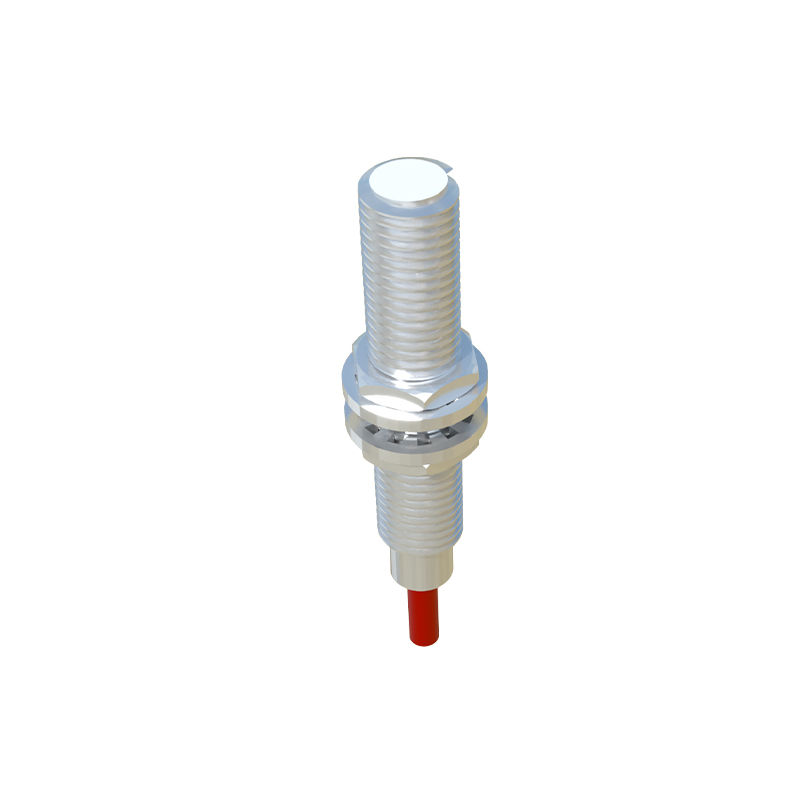
Electrical noise and load compatibility are often overlooked factors. Proximity sensors, especially inductive types, are susceptible to electromagnetic interference (EMI) from nearby motors, variable frequency drives (VFDs), or power lines. This noise can swamp the digital signal. Ensure sensor cables are shielded, with the shield properly grounded at one end only (typically the PLC cabinet). Keep sensor wiring separate from high-voltage power lines. Regarding load, every PLC digital input has a minimum "ON-state" current requirement. Some low-current output sensors, or sensors with long cable runs causing voltage drop, may not sink or source sufficient current to reliably trigger the PLC input. Consult both the sensor's residual current specification and the PLC input's minimum triggering current.
Finally, consider the sensor's physical and environmental state. Accumulation of metallic dust on an inductive sensor face can cause it to latch on. Check for physical damage, misalignment from its target, or the target itself being out of specification (too small, wrong material). Harsh environments with excessive vibration, temperature extremes, or chemical exposure can degrade sensor performance over time. A sensor may appear functional when tested statically but fail under operational vibration.
A logical troubleshooting sequence is: Observe (LEDs, PLC status) -> Verify (Specifications, Wiring) -> Isolate (Test sensor output independently) -> Measure (Voltages, Currents) -> Inspect (Physical/Environmental). Always refer to the manufacturer's documentation for specific details. By methodically eliminating potential causes—power issues, wiring errors, configuration mismatches, noise, and sensor faults—engineers can efficiently restore signal integrity and ensure the seamless operation of the automated system. Remember, the goal is not just to fix the immediate fault but to identify the root cause to prevent recurrence.