Proximity sensors are fundamental components in modern industrial automation, offering non-contact detection of objects. Understanding their working principle is crucial for engineers designing, selecting, and troubleshooting automated systems. This article provides a detailed, diagrammatic explanation of the core operating principles behind the most common types of proximity sensors.
The primary function of any proximity sensor is to detect the presence or absence of an object within a specified sensing range without physical contact. This is achieved by emitting a field or beam and monitoring changes in its return signal or properties. The main categories are Inductive, Capacitive, Ultrasonic, and Photoelectric sensors, each with distinct operating principles.
1. Inductive Proximity Sensors
The working principle of an inductive proximity sensor is based on electromagnetic induction. The core component is a coil wound around a ferrite core, connected to an oscillator. When powered, the oscillator generates a high-frequency alternating electromagnetic field at the active face of the sensor.
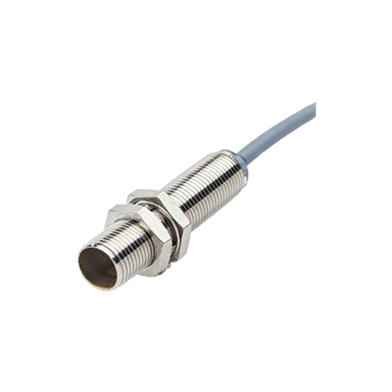
Diagram Concept: A cross-section showing the sensor housing, the ferrite core with coiled wire, the oscillator circuit block, and the emitted electromagnetic field lines.
When a metallic object (the target) enters this oscillating field, eddy currents are induced on the surface of the target. These eddy currents draw energy from the oscillator circuit, causing a reduction in the amplitude of oscillation. A threshold circuit monitors this amplitude. Once the amplitude drop exceeds a set threshold (corresponding to the sensing distance), the sensor's output solid-state switch (typically NPN or PNP) changes state, signaling detection. Inductive sensors are inherently insensitive to non-metallic materials.
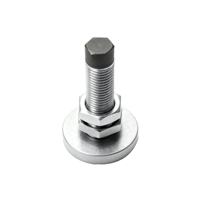
2. Capacitive Proximity Sensors
Capacitive sensors can detect both metallic and non-metallic objects, including liquids, powders, and plastics. Their principle relies on changes in capacitance. The sensor face acts as one plate of a capacitor, with the target object acting as the other plate, and the air gap as the dielectric.
Diagram Concept: A cross-section showing the sensor's active electrode (sensing face), the guard electrode (to focus the field), the internal circuitry, and the electrostatic field lines extending to the target object.
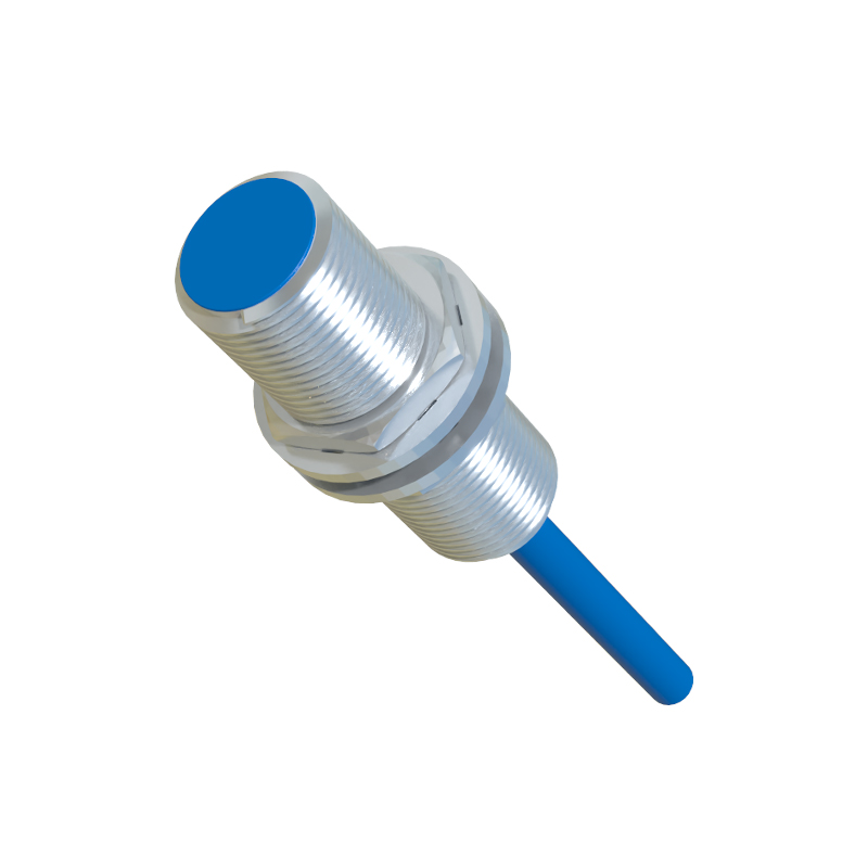
The sensor's internal circuit generates an oscillating field. As a target approaches, the capacitance between the electrode and the target increases. This increased capacitance alters the oscillation characteristics (e.g., frequency or amplitude). A trigger circuit detects this change and activates the output switch. Sensitivity adjustments allow tuning to ignore certain materials (like a container) and detect the material inside.
3. Ultrasonic Proximity Sensors
These sensors operate on the principle of sound wave reflection (echolocation). They contain a transducer that acts as both a transmitter and a receiver. The transmitter emits high-frequency ultrasonic pulses (typically 40-400 kHz). These pulses travel through the air, hit a target, and are reflected back to the receiver.
Diagram Concept: A diagram showing the sensor emitting conical sound wave pulses, the waves reflecting off a target object, and the echo returning to the sensor. A timing circuit block is highlighted.
An internal electronic timer measures the time interval between pulse emission and echo reception. Since the speed of sound in air is known, the distance to the target can be precisely calculated (Distance = (Speed of Sound × Time of Flight) / 2). The output is triggered when the calculated distance falls within the preset sensing window. They are excellent for long-range detection and level sensing of bulk materials, but are sensitive to temperature, humidity, and sound-absorbing materials.
4. Photoelectric Sensors
While often used for longer ranges, photoelectric principles are also used in proximity-style sensing. The diffuse (reflective) mode is most analogous. The sensor houses both an LED light emitter (usually infrared, red, or laser) and a phototransistor receiver. It emits a continuous or pulsed beam of light.
Diagram Concept: A diagram showing the sensor with separate emitter and receiver lenses. Light beams project out, strike the target, and are diffusely reflected back at various angles, with some light entering the receiver lens.
When a target enters the sensing field, it reflects a portion of the emitted light back to the receiver. The intensity of the received light is measured. When it surpasses a preset threshold, the output switches. Sensing distance depends on the target's color, reflectivity, and surface texture. Background suppression versions use triangulation to only detect objects within a precise close range.
Key Selection Parameters Illustrated by Principle:
Sensing Distance (Sn): The nominal operating distance. In inductive sensors, it's affected by target material and size (standard target is mild steel). In capacitive sensors, it's affected by material dielectric constant.
Hysteresis: The difference between the switch-on and switch-off points, depicted on a distance vs. output state diagram. This