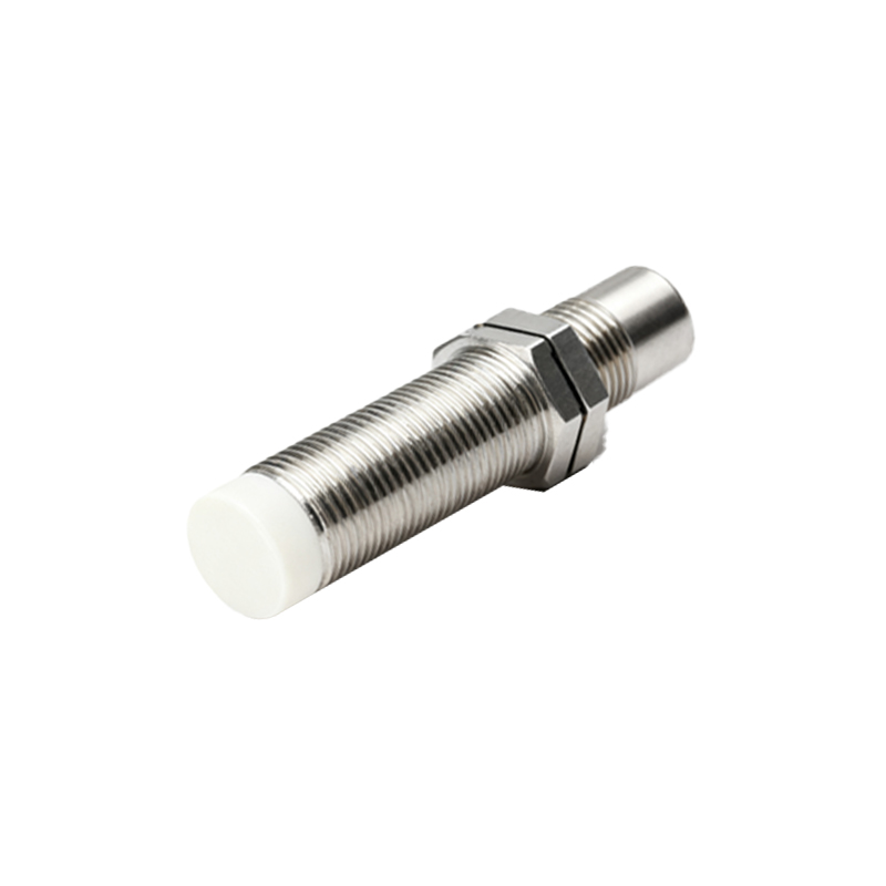
Inductive proximity sensors are widely used in industrial automation for non-contact detection of metallic objects. Their reliability is crucial for maintaining efficient production lines, but like any electronic component, they can fail. Understanding the common causes of inductive proximity sensor failure and implementing effective solutions is key to minimizing downtime and ensuring operational continuity.
One of the most frequent causes of failure is physical damage or environmental stress. Sensors are often installed in harsh industrial environments where they are exposed to mechanical impacts, excessive vibration, or crushing forces. Even a robust housing can crack under repeated stress, allowing contaminants to enter. Furthermore, extreme temperatures beyond the sensor's specified operating range can cause internal components to degrade. Prolonged exposure to high heat can melt wire insulation, damage solder joints, or alter the characteristics of the oscillator coil. Conversely, very low temperatures can make materials brittle and reduce the effective sensing distance. Solutions involve selecting sensors with appropriate IP (Ingress Protection) ratings for the environment, using protective guards or brackets to shield them from impacts, and ensuring they are rated for the ambient temperature extremes of the application. Regular visual inspections for cracks, dents, or corrosion are a simple but effective preventive measure.
Electrical overload is another primary culprit. This includes voltage spikes, incorrect power supply connections, and improper wiring. Connecting an AC sensor to a DC supply, or vice versa, will cause immediate and often catastrophic failure. Similarly, exceeding the maximum voltage rating, even momentarily from a surge on the power line, can destroy internal circuitry. Inductive loads like solenoids or motors connected near the sensor's output can generate back-electromotive force (back-EMF) that feeds back into the sensor. To combat this, always verify the sensor's voltage and current specifications against the power supply. Implementing surge protection devices on the power line and using suppression circuits (like flyback diodes for DC sensors or RC networks for AC sensors) across inductive loads connected to the sensor output can absorb damaging spikes. Proper grounding of both the sensor and the machinery is also non-negotiable for electrical stability.
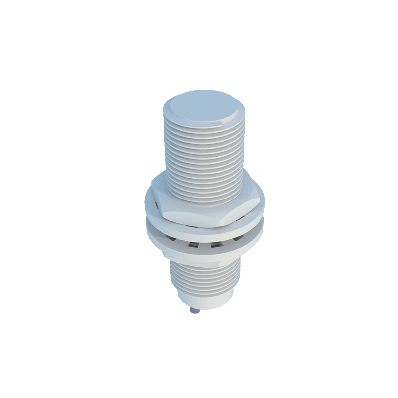
Sensor performance degradation or failure can also stem from improper installation and setup. A critical factor is the installation in metallic surroundings. If a sensor is flush-mounted into a metal bracket, it operates normally. However, if a non-flush mountable sensor is installed too close to surrounding metal, it can cause the sensor to activate prematurely or not release properly—a phenomenon known as "shielding." Incorrect sensing distance is another issue; assuming the rated sensing distance applies to all metals is a mistake. The rated distance is typically for mild steel. For stainless steel, brass, or aluminum, the effective sensing distance is reduced, sometimes significantly. This can lead to intermittent detection or missed targets. The solution is meticulous adherence to the installation guidelines. Use the correct mounting hardware, maintain the recommended clearance from surrounding metals, and always factor in the reduction factor for different target materials. Regularly testing the sensor with the actual target material at the required distance during setup is crucial.
Internal component wear and tear over time is an inevitable cause of failure. The oscillator coil, the heart of an inductive sensor, can degrade. Capacitors can dry out and lose capacitance, and output transistors can fatigue from constant switching cycles, especially under high load currents. This type of failure often manifests as a gradual reduction in sensing range, increased hysteresis, or a "sticky" output that doesn't switch cleanly. While these components have a long lifespan, they are not immortal. Implementing a predictive maintenance schedule is the best strategy. This involves periodically checking the sensor's performance against its baseline specifications, such as measuring the actual switching distance with a feeler gauge. Replacing sensors as part of a planned maintenance program, based on manufacturer-recommended lifecycles or historical failure data from your facility, is more cost-effective than dealing with unplanned line stoppages.
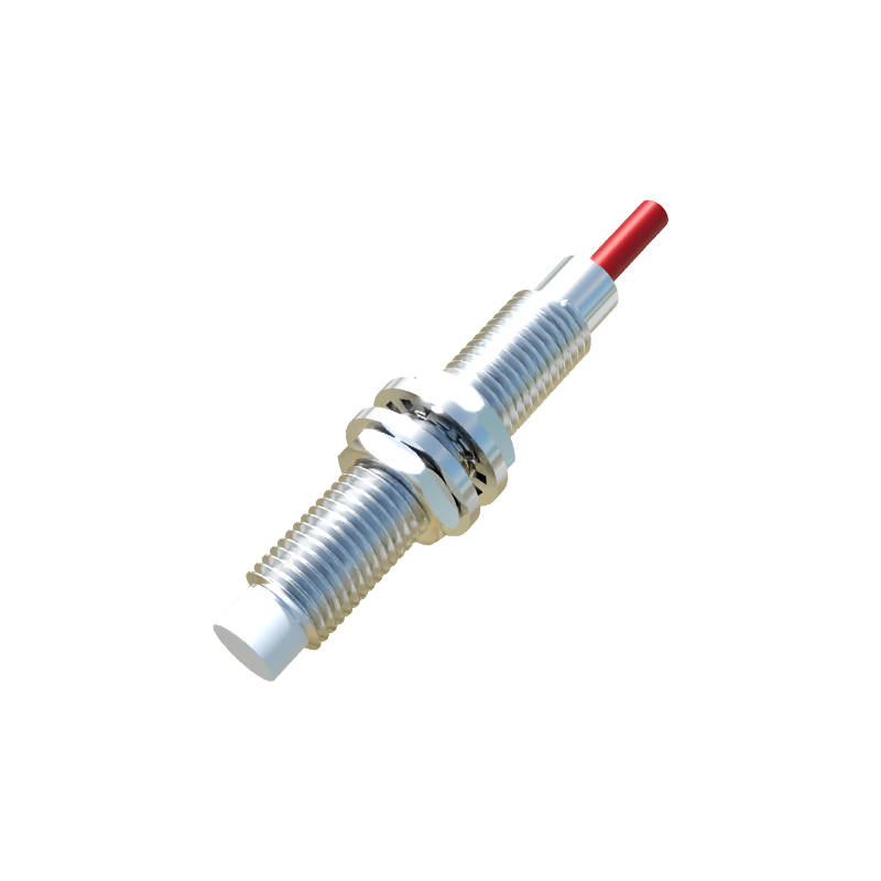
Finally, interference and incompatible targets can cause operational faults that mimic sensor failure. Strong electromagnetic fields from nearby welding equipment, large motors, or frequency drives can induce noise in the sensor's signal, causing erratic switching. Additionally, while inductive sensors detect metals, very thin foil or small, fast-moving targets may not provide enough material to trigger a reliable detection. Mitigating interference involves using shielded cables, routing sensor wires away from power cables, and selecting sensors with built-in noise immunity. For challenging targets, choosing a sensor with a higher operating frequency or a reduced sensing distance specifically designed for small parts may be necessary.
In conclusion, inductive proximity sensor failures typically originate from environmental, electrical, mechanical, or application-specific issues. A systematic approach to selection, installation, protection, and maintenance can prevent the majority of these problems. By understanding the root causes—physical damage, electrical overload, improper installation, component aging, and interference—maintenance teams can move from reactive repairs to proactive prevention, ensuring these vital components support, rather than disrupt, automated processes