Proximity switches are essential components in modern industrial automation, providing non-contact detection of objects within their sensing range. Understanding the correct wiring diagram for these sensors is crucial for ensuring reliable operation, safety, and system integration. This article details the wiring configurations for common types of proximity switches, including inductive, capacitive, and ultrasonic variants, with a focus on practical applications in electrical engineering.
Proximity switches typically consist of three main terminals: power supply (V+), ground (GND), and output (OUT). The wiring diagram varies based on the sensor's output type—either NPN (sinking) or PNP (sourcing). For an NPN proximity switch, the output terminal connects to the load, which is then linked to the positive voltage supply. When an object is detected, the switch closes the circuit to ground, allowing current to flow through the load. In contrast, a PNP switch connects the output directly to the positive supply, with the load tied to ground. This distinction is critical for compatibility with programmable logic controllers (PLCs) and other control systems.
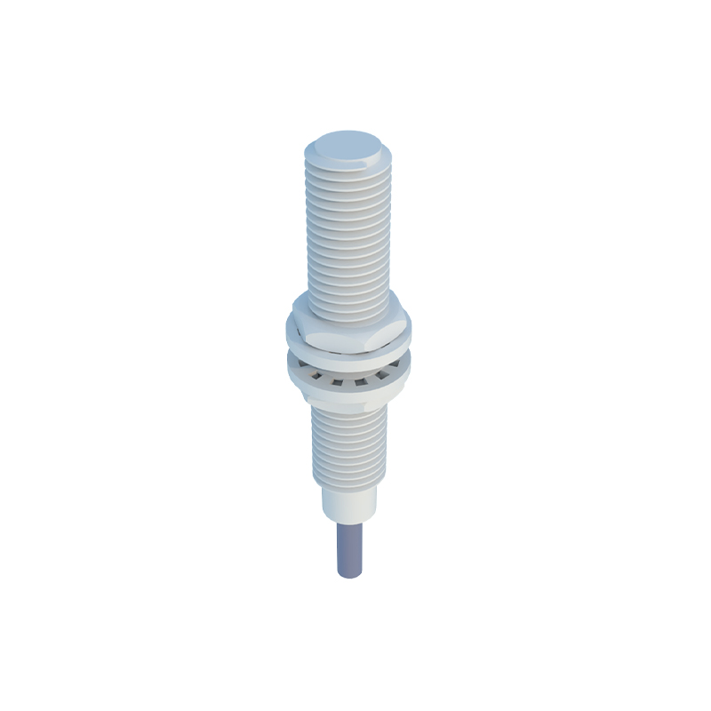
Inductive proximity switches, commonly used for metal detection, require a DC power supply ranging from 10-30V DC. The wiring diagram includes shielding to minimize electromagnetic interference (EMI), especially in high-noise industrial environments. For instance, a typical 3-wire inductive sensor features brown (V+), blue (GND), and black (OUT) wires. The brown wire connects to the positive terminal of the power source, blue to negative, and black to the input module of a PLC. Capacitive sensors, suitable for non-metallic materials, follow a similar wiring pattern but may include adjustable sensitivity settings via an additional wire.
In complex automation systems, proximity switches are often integrated into networks using bus protocols like IO-Link or PROFINET. The wiring diagram for such setups includes communication cables alongside power lines, emphasizing proper termination and grounding to prevent signal degradation. For example, an IO-Link sensor connects via a standard 3-pin M12 connector, with pin assignments for power, ground, and data transmission. Engineers must adhere to manufacturer specifications, as incorrect wiring can lead to sensor failure or erratic behavior.

Safety considerations are paramount when wiring proximity switches. Always disconnect power before installation, and use insulated tools to avoid short circuits. For hazardous locations, select intrinsically safe sensors with appropriate certifications (e.g., ATEX, IECEx). The wiring diagram should incorporate protective devices such as fuses or surge suppressors to safeguard against voltage spikes. Additionally, maintain adequate clearance between signal wires and high-voltage cables to reduce cross-talk.
Testing and validation form the final step in wiring proximity switches. Use a multimeter to verify continuity and voltage levels at each terminal. In operational tests, ensure the sensor triggers correctly within its specified sensing distance, without false positives from environmental factors like temperature fluctuations or vibration. Document the wiring diagram in system manuals for future maintenance, noting wire colors, terminal numbers, and connection points.

By mastering proximity switch wiring diagrams, engineers enhance system efficiency, reduce downtime, and support advanced automation goals. Regular training on emerging standards, such as IEC 60947-5-2, helps maintain compliance and innovation in sensor applications.