In the realm of industrial automation, proximity sensors are indispensable components for non-contact detection of metallic or non-metallic objects. Their reliability is paramount for ensuring seamless operation in applications ranging from assembly line positioning to robotic guidance. However, the physical distance between the sensor and the control system often necessitates the use of extension cables. For three-wire DC proximity sensors—arguably the most common configuration—selecting and installing the correct extension cable is a critical task that directly impacts system performance, safety, and longevity. This article delves into the technical considerations and practical guidelines for working with 3-wire proximity sensor extension cables.
Understanding the 3-Wire Configuration is the foundational step. A standard DC three-wire sensor typically comprises a brown wire (for positive supply, +V), a blue wire (for negative/common, 0V), and a black wire (for the switched output signal). The output can be either NPN (sinking) or PNP (sourcing), which determines the switching logic and how the black wire connects to the load. An extension cable must faithfully replicate this configuration, maintaining correct polarity and connection integrity across its length. Using a cable not specifically designed for this purpose can lead to voltage drop, signal degradation, or incorrect switching behavior.
Key Selection Criteria for Extension Cables
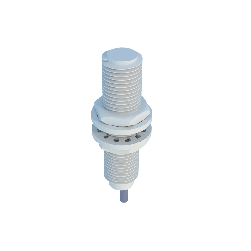
1. Conductor Specifications: The cable's current-carrying capacity must exceed the sensor's nominal current consumption. Typically, conductors with a cross-sectional area of 0.25 mm² to 0.34 mm² (AWG 24-22) are common. For longer runs, a larger gauge (e.g., 0.5 mm² or AWG 20) may be necessary to minimize voltage drop, especially on the supply lines (brown and blue). The material is almost universally tinned copper for corrosion resistance and reliable connectivity.
2. Shielding and Insulation: Industrial environments are rife with electromagnetic interference (EMI) from motors, drives, and welding equipment. A foil and/or braided shield is essential to protect the low-voltage signal on the black wire from noise, which could cause false triggering. The outer jacket material must be selected for the operating environment: PVC for general use, polyurethane (PUR) for excellent oil and chemical resistance, or thermoplastic elastomer (TPE) for high flexibility in dynamic, moving cable carrier applications.
3. Connector Compatibility: The extension cable must feature a plug that mates perfectly with the sensor's built-in connector (often M8 or M12 threaded connectors) and a socket or flying leads on the other end for connection to the controller or junction box. Using mismatched or low-quality connectors is a primary point of failure. Ensure the connector's IP (Ingress Protection) rating matches or exceeds the sensor's requirement for the installation location.
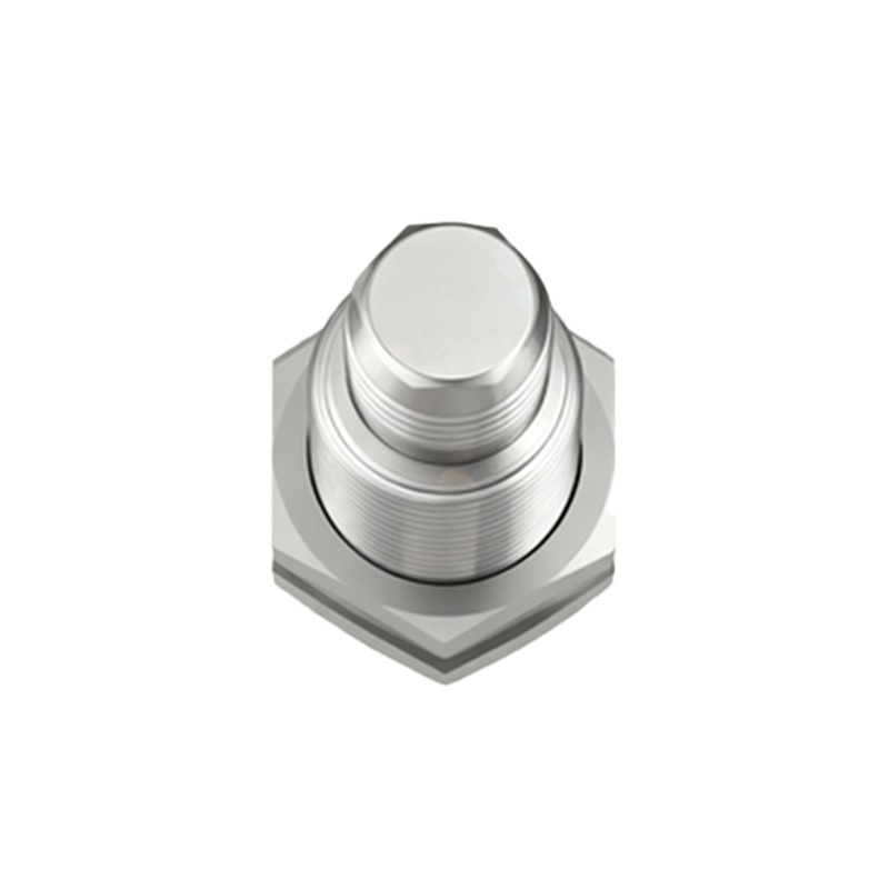
4. Length and Color Coding: Purchase only the length required. Excess cable should be neatly coiled, not tightly bundled, to avoid creating an inductive loop. Standard color coding (brown, blue, black) should be consistent throughout the cable assembly for error-free installation and maintenance.
Installation and Wiring Best Practices
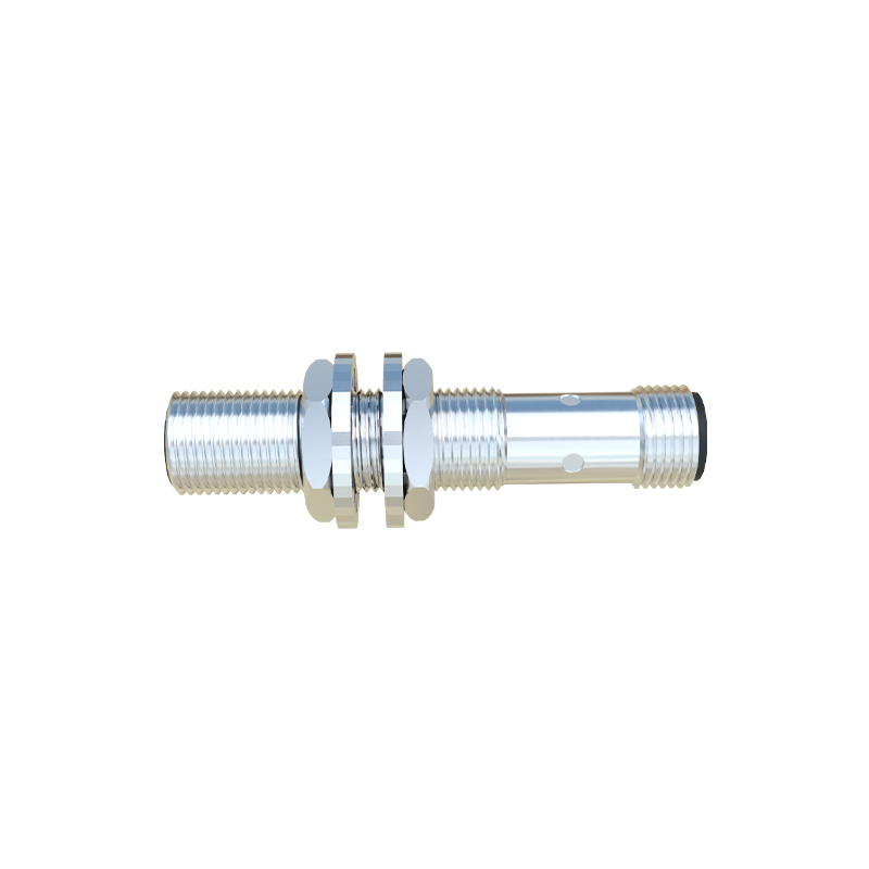
Proper installation is as crucial as cable selection. First, always power down the circuit before making connections. Route cables away from high-voltage power lines and sources of strong EMI. If parallel routing is unavoidable, maintain a minimum separation distance (e.g., 30 cm). The cable shield must be grounded at one end only, typically at the control panel side, to prevent ground loops. Use a dedicated cable gland or the connector's integrated strain relief to secure the cable and prevent tension from being transferred to the solder points or terminals.
For long-distance extensions exceeding 50-100 meters, voltage drop calculations become mandatory. Use the formula: Voltage Drop = 2 Length Current Resistance per meter. Ensure the voltage at the sensor terminals remains within its specified operating range (e.g., 10-30 VDC). In such cases, using a heavier gauge cable for the supply lines (brown/blue) while maintaining the signal wire gauge can be a cost-effective solution.
Troubleshooting Common Issues
Many field problems with proximity sensors trace back to the cabling. Intermittent operation often points to a broken shield, poor connector contact, or a compromised wire within a moving cable carrier. Constant activation may indicate a short circuit between the output (black) and positive supply (brown), often due to pinched insulation. If a sensor fails to operate, use a multimeter to verify that the correct supply voltage is present at the sensor's connector pins via the extension cable. A systematic check of continuity and insulation resistance between conductors can isolate most cable faults.
In conclusion, the extension cable is not merely a passive length