In the complex and electrically noisy environment of modern industrial automation, the reliable operation of sensors is paramount. Among these, proximity switch sensors stand as critical components for non-contact detection of objects. However, their performance can be severely compromised by electromagnetic interference (EMI), radio frequency interference (RFI), and other environmental disturbances. This article delves into the operational principles of standard inductive and capacitive proximity sensors and, more importantly, explores the sophisticated engineering behind anti-interference designs that ensure unwavering reliability.
At its core, a standard inductive proximity sensor generates a high-frequency electromagnetic field via an oscillator circuit connected to a coil wound around a ferrite core. When a metallic object (the target) enters this field, eddy currents are induced on the object's surface. These currents draw energy from the oscillator, causing its amplitude to decrease. A subsequent evaluation circuit detects this amplitude drop and triggers a solid-state output switch. Capacitive sensors operate on a similar principle but respond to both conductive and non-conductive materials by detecting changes in capacitance between the sensor's active surface and the target.
The vulnerability of these sensors lies in their inherent design. The oscillator's high-frequency signal can be susceptible to external EMI from sources like variable frequency drives (VFDs), welding equipment, large motors, and communication devices. This external noise can falsely modulate the oscillator's amplitude, leading to phantom triggering or failure to detect a valid target. Furthermore, sensors placed in close proximity to each other can interfere mutually through their emitted fields, a phenomenon known as cross-talk.
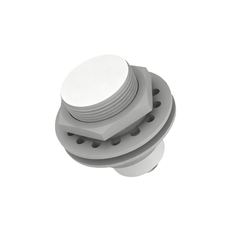
To combat these challenges, anti-interference proximity sensors incorporate multiple layers of defensive strategies in their design and signal processing.
1. Shielding and Housing Design: The most fundamental step is physical shielding. Sensors are housed in robust, metallic casings (often stainless steel or brass) that act as a Faraday cage, attenuating external RFI. The sensing face, however, must remain unshielded to allow the field to emanate. Advanced designs use specially shaped shields and ferrite cores that focus the electromagnetic field tightly in front of the sensor, minimizing lateral spread and thus reducing both susceptibility to external noise and potential for cross-talk.
2. Advanced Oscillator Circuitry and Modulation Techniques: Instead of a simple continuous-wave oscillator, anti-interference models often use amplitude-modulated (AM) or frequency-modulated (FM) signals. By encoding the detection signal with a specific modulation pattern, the sensor's evaluation circuit can be designed to only recognize changes in that specific pattern. Random environmental noise, which lacks this modulation, is effectively filtered out. This is analogous to tuning a radio to a specific station's frequency, ignoring static.
3. Sophisticated Signal Evaluation and Filtering: The heart of anti-interference capability lies in the integrated circuit's evaluation logic. Modern sensors employ microprocessors that implement digital signal processing (DSP) algorithms. These algorithms can include:
Band-Pass Filtering: Allowing only signals within the sensor's specific operating frequency band to pass through.
Time-Domain Analysis: Requiring that a signal change (amplitude drop) persists for a minimum, programmable duration before triggering an output. This rejects short-duration noise spikes.
Hysteresis and Threshold Adjustment: Implementing a significant difference between the "switch-on" and "switch-off" points, preventing rapid toggling due to signal fluctuations near the detection threshold.
4. Output Stage Protection: The sensor's output transistor is protected against voltage spikes and surges from the load or supply line using built-in protection diodes, RC snubber circuits, or varistors. This ensures that electrical noise on the output lines does not damage the sensor or cause false signals to be sent to the controller (PLC).
5. Synchronous Operation (for multi-sensor setups): In applications with dense sensor arrays, synchronous or clocked operation can be used. A master controller or the sensors themselves synchronize their oscillation cycles, ensuring they are active and sampling at different times, thereby eliminating cross-talk.
The benefits of implementing true anti-interference sensors are substantial. They directly translate to reduced machine downtime, fewer production errors, lower maintenance costs, and enhanced overall system safety. When selecting such a sensor, key specifications to scrutinize include the stated immunity to EMI/RFI (often tested per IEC/EN 60947-5-2 or similar standards), the operating frequency shift capability, the shielding type (e.g., flush-mounted or non-flush), and the hysteresis value.
In conclusion, while the basic principle of proximity detection is straightforward, ensuring reliable operation in harsh industrial environments demands sophisticated anti-interference engineering. Through a combination of shielded mechanical design, modulated field generation, intelligent digital signal