In industrial automation, proximity sensor switches are indispensable components for detecting the presence or absence of objects without physical contact. Their integration with Programmable Logic Controllers (PLCs) forms the backbone of countless control systems, from assembly lines to packaging machinery. This guide provides a detailed, professional walkthrough on how to correctly wire and configure these sensors with a PLC, ensuring reliable operation and system integrity.
First, it is crucial to understand the fundamental types of proximity sensors, as their wiring differs. The two primary categories are sourcing (PNP) and sinking (NPN) sensors, defined by their output transistor configuration. A PNP sensor switches the positive voltage to the load, while an NPN sensor switches the negative or ground side. Most modern PLC digital input (DI) modules are designed to be compatible with both types, but verifying the module's specifications is the mandatory first step. Consult the PLC hardware manual to confirm the acceptable voltage range (commonly 24V DC) and the input circuit type (sinking or sourcing).
The core connection involves three main components: the proximity sensor's power supply, its output signal, and the PLC's input channel. For a standard 3-wire DC proximity sensor, you will typically have brown (or red) for positive (+V), blue for negative (0V or common), and black (or white) for the output signal. Here is the standard procedure:
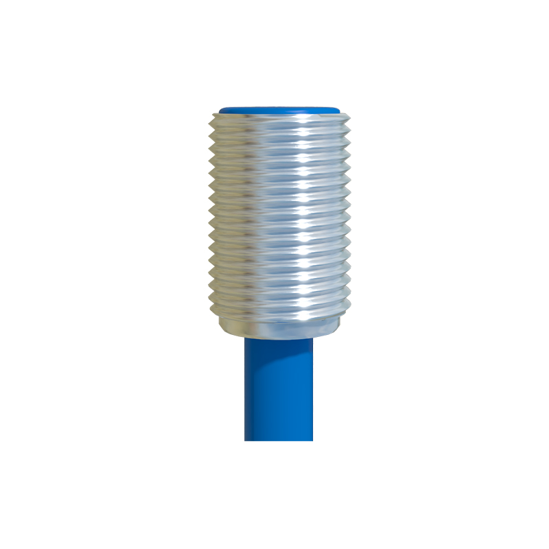
1. Power Supply Connection: Provide a stable DC power source, typically 24V, matching the sensor's rated voltage. Connect the positive terminal of the power supply to the sensor's brown wire. Connect the negative terminal of the power supply to the sensor's blue wire. This same power supply negative must also be connected to the PLC's common terminal for the input module (often labeled as "COM" or "M").
2. Signal Output to PLC Input: Connect the sensor's black (output) wire to a specific terminal on the PLC's digital input module (e.g., I0.0, I0.1). This completes the circuit. When the sensor detects a target, its internal transistor switches, allowing current to flow from the sensor's output, into the PLC input point, and back to the common (COM). This current flow is interpreted by the PLC as a logic HIGH or "1" state.
3. Critical Considerations:
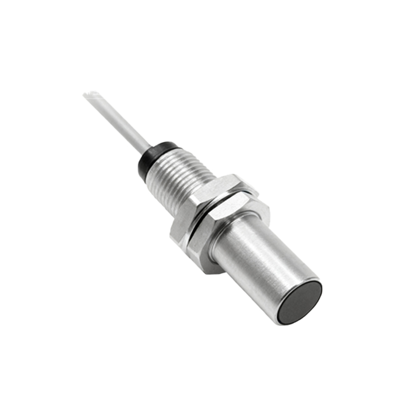
Sourcing vs. Sinking: If your PLC input module is configured as sinking (common is positive), you must use a PNP (sourcing) sensor. If the module is sourcing (common is negative), you must use an NPN (sinking) sensor. Mismatching can lead to non-operation or damage.
Shielded Cable: For sensors operating in electrically noisy environments, use shielded cables. Connect the cable shield to a functional earth ground at one end only (usually the PLC cabinet ground) to prevent ground loops.
Load Considerations: While PLC inputs present a high impedance, ensure the sensor's output current rating is not exceeded. PLC input points typically draw only a few milliamps, well within the capacity of standard sensors.
Protective Circuits: Although many sensors have built-in protection, consider adding external components like flyback diodes for inductive loads or fuses for overcurrent protection on the power line in harsh applications.
After physical wiring, configuration within the PLC programming software is necessary. This involves defining the used input address in the control logic. For instance, a ladder logic program might use a normally open contact (--| |--) addressed as I0.0. When the sensor activates (I0.0 becomes TRUE), the contact closes, allowing logic continuity to trigger an output, such as starting a motor or incrementing a counter.
Testing and diagnostics are final, essential steps. Use a multimeter to verify voltage at the sensor terminals. Actuate the sensor and observe the corresponding LED indicator on both the sensor body and the PLC input module. Monitor the input status bit in the PLC's software to confirm it toggles correctly. Common issues include incorrect power polarity, open circuits, mismatched sensor/PLC types, or insufficient sensing distance.
In summary, successful integration of a proximity sensor with a PLC hinges on correct identification of sensor type (PNP/NPN), adherence to the PLC input module's electrical requirements, meticulous wiring following color codes and schematics, and proper software addressing. By following this systematic approach, engineers and technicians can ensure robust, fault-free communication between field devices and the control system, maximizing uptime and operational efficiency in any automated industrial setting.