In the realm of industrial automation and precision machinery, the reliable operation of proximity sensors is non-negotiable. The 14PM series, a widely adopted inductive proximity sensor known for its robust metal detection capabilities, occasionally presents a critical failure mode: the sensor reads nothing at all. This complete lack of output, as opposed to intermittent or erratic readings, halts production lines and demands immediate, systematic troubleshooting. Understanding the root causes and implementing effective solutions requires a methodical approach grounded in electrical engineering principles.
The primary symptom is straightforward: the sensor fails to indicate the presence of a valid target within its specified sensing range, regardless of target material, size, or distance. The output state (PNP or NMP) remains unchanged. The first and most crucial step is to verify power supply integrity. A 14PM sensor typically operates within a 10-30V DC range. Using a calibrated multimeter, measure the voltage directly at the sensor's terminals. A reading below the minimum threshold, even by a small margin, can prevent operation. Check for voltage drops caused by long cable runs, undersized wiring, or faulty connections in the supply circuit. Simultaneously, verify the grounding connection is secure and low-resistance, as poor grounding is a frequent culprit for sensor malfunction.
Assuming power is confirmed, the next phase involves isolating the sensor from the load. Disconnect the sensor's output wire from the PLC input module or subsequent controller. Using the multimeter in appropriate mode (voltage or continuity, depending on wiring), test the sensor's output directly. Actuate the sensor by bringing a standard target (e.g., a piece of mild steel) directly to its face. A healthy sensor will show a clear change in output state. If there is no change, the fault likely resides within the sensor itself. However, if the sensor functions correctly when disconnected, the problem shifts to the load side. An overloaded input, a short circuit in the cabling, or a damaged PLC input channel can sink excessive current, effectively "holding" the output in one state and creating the illusion of a dead sensor. Always check the load's specifications against the sensor's maximum switching current.

Environmental factors must be rigorously assessed. The 14PM is shielded and designed for industrial environments, but extreme conditions can cause failure. Accumulation of metallic dust or chips on the sensor face can effectively shield its electromagnetic field, preventing detection. Thoroughly clean the sensing face with a non-abrasive cloth and isopropyl alcohol. Consider physical damage: impacts can dislodge internal coils or crack the ferrite core. Inspect the housing for dents or cracks. Furthermore, ensure the target meets specifications. While inductive sensors detect metals, different materials affect the sensing distance. A target made of stainless steel or aluminum will have a reduced effective range compared to mild steel. The target must also be of sufficient size; a target smaller than the sensor's face diameter may not be detected reliably.
Electrical interference (EMI) is another potential, though less common, cause for a complete read failure. High-frequency noise from variable frequency drives (VFDs), welding equipment, or large solenoids can swamp the sensor's oscillator circuit. Examine the installation. Are sensor cables run in separate conduits from power cables? Is shielding properly grounded at only one end? Implementing best practices—using shielded cables, ensuring proper grounding, and maintaining distance from noise sources—can resolve interference-related issues.
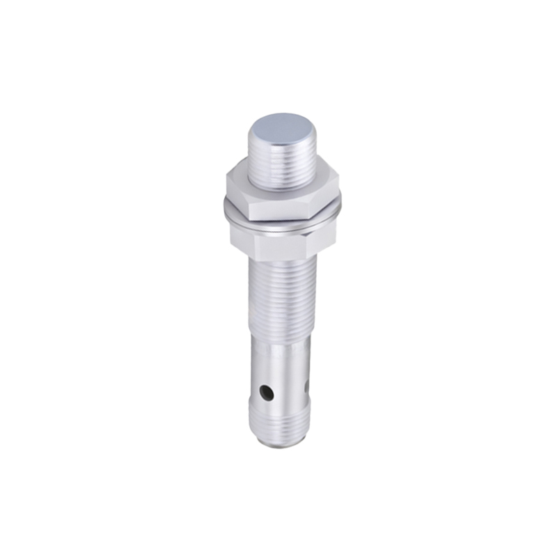
If all external factors are eliminated, the conclusion is an internal sensor failure. The internal oscillator, the core component generating the electromagnetic field, may have failed. The output switching transistor or the associated circuitry could be damaged, possibly from a voltage spike or surge. In such cases, sensor replacement is the only viable solution. Before installing a new unit, it is prudent to install a protective device such as a surge suppressor or a zener diode barrier in the supply line to mitigate future transient voltage events.
In summary, diagnosing a 14PM proximity sensor with no output mandates a sequential process: Power Verification -> Load Isolation -> Environmental & Target Check -> EMI Evaluation -> Internal Diagnosis. Documenting each step and its result is key to efficient repair and future preventative maintenance. Proactive measures, including regular inspection of connections, cleaning schedules, and environmental controls, significantly reduce the incidence of such critical failures, ensuring continuous operational uptime and system reliability.