In the realm of industrial automation and control systems, proximity sensors are indispensable components for non-contact detection of metallic or non-metallic objects. Among the various configurations, the 3-wire proximity sensor is arguably the most common and versatile type used in modern machinery. Understanding its wiring diagram is fundamental for engineers, technicians, and maintenance personnel to ensure reliable operation, safety, and system integrity. This article provides a detailed, professional guide to the 3-wire proximity sensor connection diagram, adhering to standard international practices and electrical conventions.
A 3-wire proximity sensor typically operates on a DC power supply, commonly 10-30V DC. The three wires are distinctly color-coded to denote their function: Brown, Blue, and Black (or sometimes another color like White or Gray). This color scheme is largely standardized per IEC standards, though it is always crucial to verify the manufacturer's datasheet.
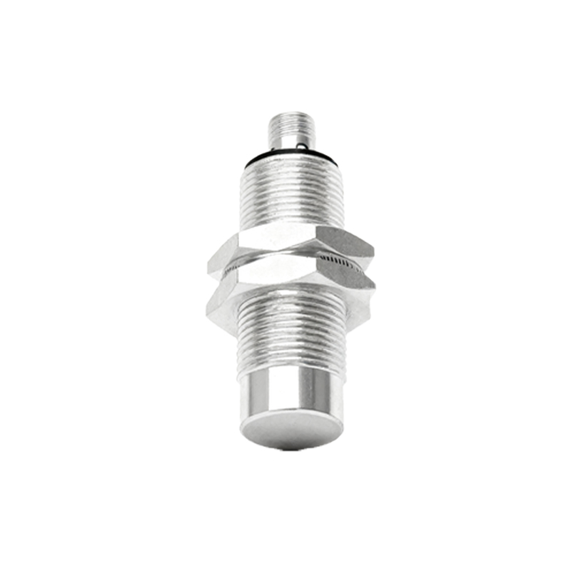
Wire Functions and Standard Color Codes:
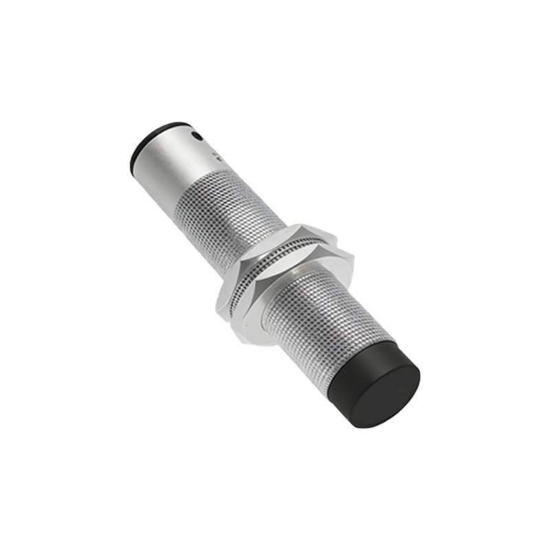
1. Brown Wire: This is the positive supply line (+V or V+). It must be connected to the positive terminal of the DC power source.
2. Blue Wire: This is the negative supply line (0V or COM). It must be connected to the negative terminal or common ground of the DC power source.
3. Black Wire: This is the output signal line. The state of this wire changes based on the sensor's detection status. It is the critical interface to the Programmable Logic Controller (PLC), relay, or other control device.
Understanding the Output Types:
The functionality of the black output wire defines the sensor's type. There are two primary configurations:
NPN (Sinking) Output: In an NPN sensor, the black wire acts as a switched negative. When the sensor is activated (detects a target), it connects the black output wire internally to the blue wire (0V), effectively "sinking" current to ground. The load (e.g., a PLC input) must be connected between the black wire and the positive supply (+V).
PNP (Sourcing) Output: In a PNP sensor, the black wire acts as a switched positive. When activated, it connects the black output wire internally to the brown wire (+V), "sourcing" current from the supply. The load must be connected between the black wire and the negative supply (0V).
The Standard Connection Diagram:
The connection is straightforward but must be precise. For a typical setup involving a DC power supply and a PLC digital input module, follow this diagrammatic logic:
1. Power Supply Connection: Connect the Brown wire to the +24V DC terminal of your power supply. Connect the Blue wire to the 0V DC (common) terminal of the same power supply. This provides the sensor with the necessary operating voltage.
2. Output to Load Connection:
For a PNP Sensor: Connect the Black wire to one terminal of your load (e.g., PLC input channel I0.0). Connect the other terminal of that same PLC input to the 0V DC (common) of the power supply. When the PNP sensor detects an object, it sources +24V to the PLC input, signaling a HIGH or TRUE state.
For an NPN Sensor: Connect the Black wire to one terminal of your PLC input. Connect the other terminal of that PLC input to the +24V DC of the power supply. When the NPN sensor activates, it sinks current to 0V, pulling the PLC input to a LOW state, which is typically interpreted as a TRUE or activated condition depending on the PLC's input card configuration (sinking vs. sourcing).
Critical Considerations for Reliable Operation:
Power Supply Quality: Use a regulated, stable DC power supply. Voltage spikes or noise can cause erratic sensor behavior or damage.
Load Compatibility: Always match the sensor output type (NPN/PNP) with the input circuit of your controller. Connecting a PNP sensor to a sinking input, or vice versa, will not work and may cause issues.
Shielded Cable for Noise Immunity: In electrically noisy environments (near VFDs, large motors, welding equipment), use shielded cable. Connect the cable shield to a proper functional earth ground at one end only (usually the control panel end) to prevent ground loops.
Short-Circuit and Overload Protection: While many sensors have built-in short-circuit protection, it is good practice to fuse the supply line (brown wire) and, if necessary, the output line. Ensure the load current does not exceed the sensor's maximum switching capacity.