As an experienced electrical engineer specializing in industrial automation, I have encountered numerous proximity sensors in various applications. Among them, the square-type inductive proximity sensor is a common and robust component used for position detection, object counting, and machine safety. This article provides a detailed, step-by-step disassembly guide and an analysis of the internal construction of a typical square proximity sensor, adhering to professional engineering standards and safety practices.
Before initiating any disassembly, ensure the sensor is completely disconnected from all power sources and removed from its mounting location. Verify the absence of voltage using a multimeter. Wear appropriate personal protective equipment (PPE), including safety glasses and anti-static gloves, to prevent injury and protect sensitive electronic components from electrostatic discharge (ESD).
The external housing of a standard square proximity sensor is typically molded from rugged engineering plastic (like PBT or PPS) or nickel-plated brass for metallic versions, designed to meet IP67 or higher ingress protection ratings. The first step is to locate and remove the mounting brackets or nuts if present. Most square sensors feature a threaded barrel section for mounting. The sensing face is usually clearly marked and should be handled with care to avoid scratches that could affect performance.
Using a suitable size hex key or screwdriver, carefully unscrew and remove the four small screws located at the corners of the sensor's rear face (the end opposite the sensing face). In some models, these screws might be concealed under a label or a plastic cover. Keep all screws and small parts organized. Once the screws are removed, the main housing can be gently separated. It often consists of two halves: the front body containing the sensing coil assembly and the rear body housing the electronics. A silicone gasket or O-ring provides the seal between these halves—inspect it for any signs of wear or damage.
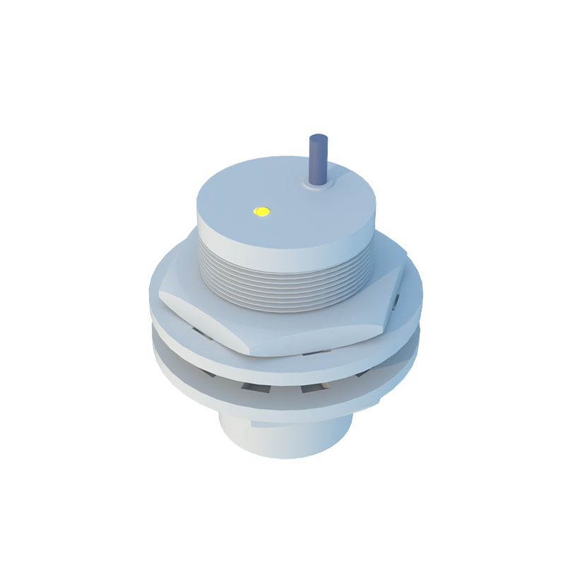
Upon opening, the internal layout is revealed. The core component is the oscillator coil, wound around a ferrite core, located directly behind the sensing face. This coil generates a high-frequency electromagnetic field. When a metallic target enters this field, eddy currents are induced, causing a change in the oscillation amplitude. This change is detected by the subsequent circuitry. The coil is potted in a solid epoxy resin compound for mechanical stability, moisture resistance, and to dampen vibrations. Do not attempt to remove this potting material, as it will permanently damage the coil.
The printed circuit board (PCB) is securely fastened to the rear housing. It typically hosts several key integrated circuits: the oscillator circuit, a Schmitt trigger for signal conditioning, an output amplifier (for transistor-based sensors), and often a voltage regulator. For DC sensors, the output switching element is usually a PNP or NPN transistor. For AC/DC universal models, a solid-state relay (thyristor or triac) is common. Trace the connections from the coil to the PCB via thin, insulated wires. Note the color coding: often red for power (V+), blue or black for common (0V), and black or white for the output signal.
The output leads or the connector block are molded into the housing. Examine the strain relief where the cable enters the body—this is a critical point for mechanical integrity. If the sensor has an LED status indicator, it will be a small surface-mount LED on the PCB, aligned with a light pipe in the housing.
Reassembly is the reverse process. Ensure the sealing gasket is correctly seated in its groove. Align the two housing halves precisely and tighten the screws evenly in a cross pattern to avoid distorting the housing and compromising the seal. Do not over-torque the screws. Before re-energizing, it is advisable to perform a basic functional test with a multimeter in diode-check or resistance mode, if possible, according to the sensor's datasheet.
Understanding the internal build of a square proximity sensor not only aids in troubleshooting and repair but also informs better selection for specific environmental conditions (e.g., resistance to welding spatter, cutting fluids, or extreme temperatures). The robust potting, quality seals, and simple yet effective circuit design explain the longevity and reliability of these devices in harsh industrial settings. Always consult the manufacturer's documentation, as designs can vary between brands and sensing technologies (inductive, capacitive, ultrasonic).