In the realm of industrial automation, the integration of proximity sensors with Programmable Logic Controllers (PLCs) forms a critical link for monitoring and control. Proximity sensors, which detect the presence or absence of an object without physical contact, provide essential input data to the PLC. This data drives logic-based decisions, controlling outputs like motors, valves, or alarms. A correct and reliable connection is paramount for system integrity. This guide details the standard procedures for wiring various types of proximity sensors to a PLC input module.
First, understanding the sensor type is crucial. Proximity sensors are broadly categorized by their output configuration and sensing technology. The two primary output types are NPN (sinking) and PNP (sourcing), named for the type of transistor used in their output stage. Inductive sensors detect metallic objects, while capacitive sensors can detect both metallic and non-metallic materials. Regardless of the technology, the wiring principle to a PLC digital input remains consistent for a given output type.
A standard PLC digital input module is designed to receive a DC voltage signal, commonly 24VDC, which is standard in industrial environments. The input point acts as a switch to ground or to positive, depending on its internal circuit design. Most modern PLC input cards can be configured or are universally compatible with both NPN and PPN sensors, but verifying the manufacturer's specifications is always the first step.
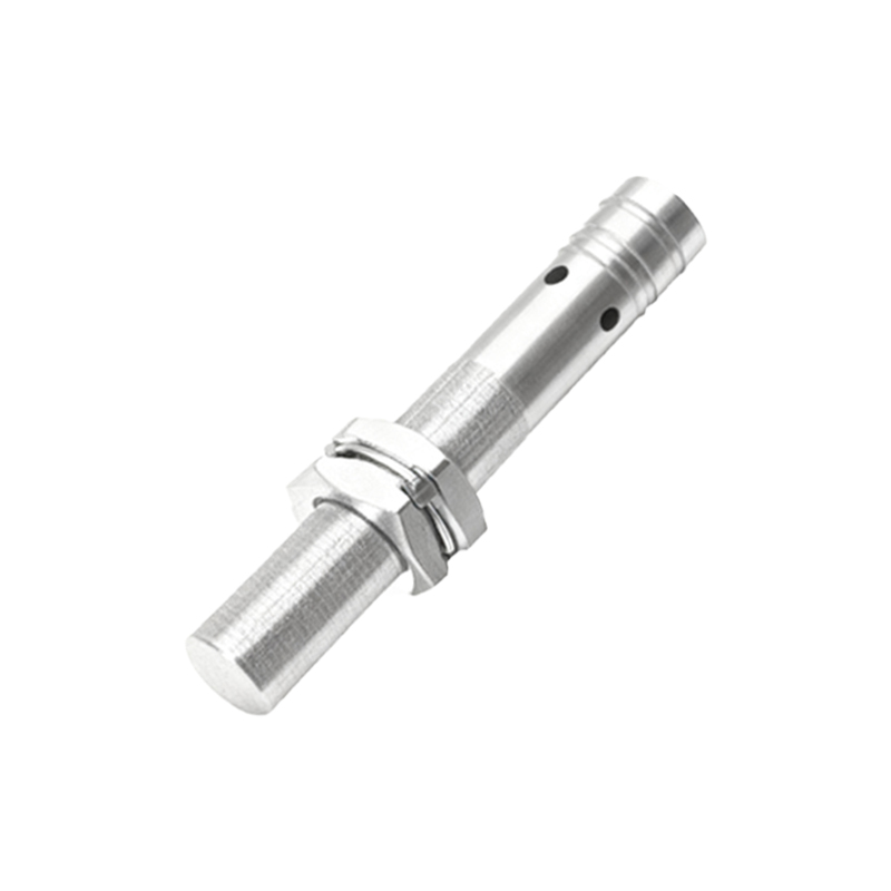
Wiring a PNP (Sourcing) Proximity Sensor:
A PNP sensor switches the positive voltage. It has three wires: Brown (typically +24VDC), Blue (typically 0VDC or Common), and Black (the switched output signal).
1. Connect the Brown wire from the sensor to the +24VDC power supply terminal.
2. Connect the Blue wire from the sensor to the 0VDC (Common) of the same power supply.
3. Connect the Black (output) wire from the sensor to the designated terminal of the PLC input channel (e.g., I0.0).
4. Finally, connect the common terminal of the PLC input module (often labeled "M" or "COM") to the 0VDC (Common) of the power supply.
In this configuration, when the sensor detects an object, it "sources" or provides +24VDC on the Black wire to the PLC input. The PLC input circuit closes to its internal common (0VDC), registering a logic HIGH or "1" state.
Wiring an NPN (Sinking) Proximity Sensor:
An NPN sensor switches the negative or 0V path. Its wire colors are identical: Brown (+24VDC), Blue (0VDC), and Black (switched output).
1. Connect the Brown wire to +24VDC.
2. Connect the Blue wire to 0VDC.
3. Connect the Black (output) wire to the PLC input terminal.
4. The key difference: Connect the common terminal of the PLC input module to the +24VDC of the power supply.
Here, when activated, the NPN sensor "sinks" current, connecting the PLC input terminal to 0VDC (through the Blue wire). Since the PLC input common is at +24VDC, a completed circuit creates a voltage drop, registering a logic LOW or "1" state (note: logic interpretation can vary by PLC, but the physical activation is confirmed).
For 2-wire AC/DC sensors, wiring is simpler but requires careful consideration of the residual current ("leakage current") when off. The two wires are connected in series with the load (the PLC input). One wire connects to the power supply (L+ or L1), and the other connects to the PLC input. The PLC input's common is then connected to the other side of the power supply (M or N). A bleeder resistor may be necessary across the PLC input if leakage current is high enough to falsely trigger the input.
Critical Best Practices:
Power Supply: Always use a clean, regulated DC power supply. Shielded cables are recommended for long runs or electrically noisy environments.
Grounding: Properly ground the sensor housing and the shield of the cable (if present) to the central ground point to mitigate electromagnetic interference (EMI).
PLC Input Type: Confirm if your PLC input is sinking or sourcing. A universal input module simplifies this. Mismatching a PNP sensor with a sinking-only input (or vice-versa) will not work.
Diagnostic LEDs: Utilize the indicator LEDs on both the sensor and the PLC input module for quick troubleshooting. A lit sensor LED with no PLC input activation immediately points to a wiring error.