Replacing proximity sensor components is a common maintenance task in industrial automation and electrical systems. Whether due to wear, damage, or upgrading needs, proper replacement ensures reliable operation and minimizes downtime. This guide outlines a systematic approach to replacing proximity sensor raw materials and components, adhering to industry best practices.
First, safety is paramount. Always de-energize the electrical circuit and lock out/tag out (LOTO) the power source before starting any work. Wear appropriate personal protective equipment (PPE), such as insulated gloves and safety glasses, to prevent electrical shocks or injuries from sharp edges. Verify the absence of voltage using a multimeter or voltage tester.
Identify the sensor type and specifications. Proximity sensors come in various forms—inductive, capacitive, ultrasonic, and photoelectric—each with unique components. Check the manufacturer’s datasheet for details like sensing range, output type (e.g., NPN/PNP), voltage rating, and housing material. Note the part numbers and compatibility requirements. For raw material replacement, this may involve swapping out sensing elements, coils, or oscillator circuits in inductive sensors, or transducers in ultrasonic models.
Gather the necessary tools and replacement parts. Common tools include screwdrivers, wrenches, wire strippers, and soldering equipment. Ensure the new components match the original specifications. If upgrading, confirm that the replacement materials (e.g., nickel-plated brass for housings or ferrite cores for coils) meet environmental conditions like temperature, humidity, and chemical exposure.
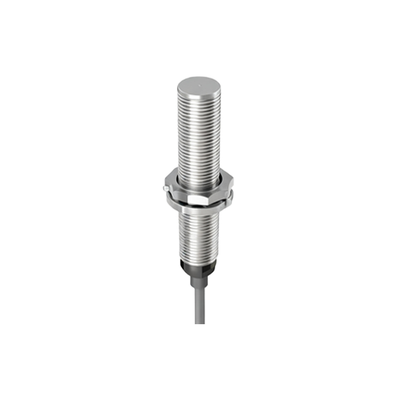
Disconnect the sensor from the system. Remove wiring connections carefully, labeling each wire to simplify reinstallation. For embedded sensors, unscrew or unclip the housing. Inspect the old component for signs of failure, such as corrosion, cracks, or burnt areas, which can inform future maintenance schedules.
Replace the raw materials or internal parts. For example, in an inductive proximity sensor, you might replace the coil wound around a ferrite core. Desolder the old coil leads, remove the core, and install a new one with identical turns and gauge. Secure it with epoxy or mounting brackets to prevent vibration damage. In capacitive sensors, replace the electrode plates or dielectric materials, ensuring proper alignment. Reassemble the housing tightly to maintain IP ratings for dust and water resistance.
Reconnect and test the sensor. Rewire the connections according to the diagram, double-checking polarity for DC sensors. Gradually restore power and observe the sensor’s indicator LED (if available). Use a target object to verify the sensing range and output signal. Measure the response time and consistency with an oscilloscope or PLC monitor. Calibrate if necessary, adjusting potentiometers or settings per the manual.
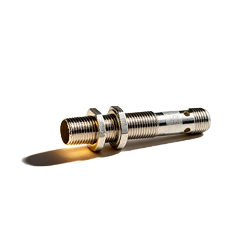
Document the replacement. Record the date, replaced components, and any deviations from standard procedures. This aids in troubleshooting and inventory management. Regular maintenance, such as cleaning sensing surfaces and checking connections, can extend the sensor’s lifespan.
In summary, replacing proximity sensor materials requires precision and adherence to safety protocols. By following these steps, engineers can ensure optimal performance and reduce system failures in industrial applications.