Proximity sensors are indispensable components in modern industrial automation, providing non-contact detection of objects. Among the various output configurations, the NPN type is widely used and fundamental to understanding sensor wiring and integration. This article delves into the operating principle of NPN output in proximity sensors, explaining its function in a clear, technical manner.
At its core, a proximity sensor detects the presence or absence of a target object within its sensing range without physical contact. Common types include inductive (for metals), capacitive (for various materials), and photoelectric sensors. Regardless of the sensing technology, the electrical output stage often utilizes a semiconductor switching device. This is where the NPN configuration comes into play.
The terms "NPN" and "PNP" refer to the type of bipolar junction transistor (BJT) used in the sensor's output circuit. A transistor is a solid-state switch that controls a larger output current using a smaller input signal. An NPN transistor is constructed by sandwiching a P-type semiconductor layer between two N-type layers. In a typical proximity sensor with an NPN output, the transistor is connected in a specific way to function as a low-side switch.
Here is a step-by-step breakdown of the NPN output principle:
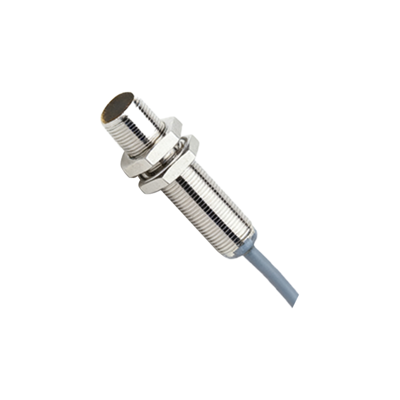
1. Internal Operation: When the sensor's sensing element (e.g., an oscillator coil in an inductive sensor) detects a valid target, it triggers an internal circuit. This circuit sends a small control current to the base (B) terminal of the NPN transistor.
2. Transistor Switching: The application of a positive signal to the base (relative to the emitter) allows current to flow from the collector (C) to the emitter (E). In essence, the transistor "turns on" or saturates, creating a low-resistance path between its collector and emitter terminals.
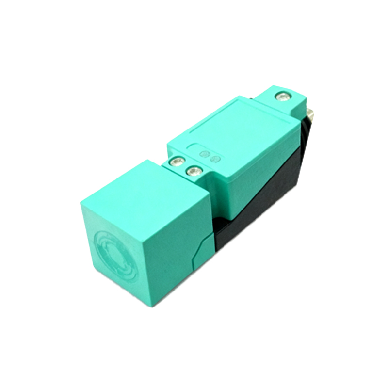
3. Circuit Connection - The Low-Side Switch: In a standard DC sensor wiring scheme, the sensor has three wires: Brown (V+, e.g., +24V DC), Blue (V-, 0V or Common), and Black (Output Signal). The NPN transistor's emitter is connected internally to the Blue wire (0V). The collector is connected to the Black output wire.
4. The Load: The device being controlled by the sensor (the load), such as a programmable logic controller (PLC) input, a relay coil, or an indicator lamp, is connected between the Black output wire and the positive supply (Brown wire). This is a crucial point: the load is connected between the sensor's output and the positive voltage rail.
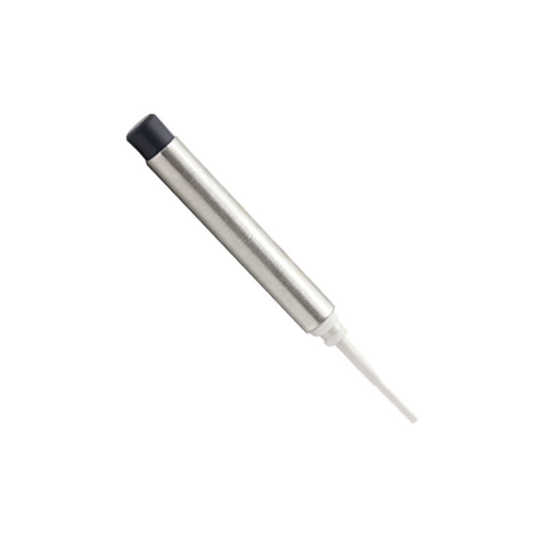
5. Current Path (Sinking): When the target is present and the NPN transistor switches ON, it effectively connects the Black output wire to the Blue wire (0V). This completes the circuit for the load. Current flows from the positive supply (Brown), through the load, into the Black wire, down through the activated transistor, and out the Blue wire back to the power supply negative. Because the NPN transistor "sinks" the current from the load to ground (0V), an NPN output is also called a sinking output.
6. State Representation: When no target is detected, the transistor is OFF. The output (Black wire) is in a high-impedance state (effectively open circuit), and no current flows to the load. When a target is detected, the transistor is ON, sinking current to ground, and the voltage at the Black wire drops close to 0V (a logic LOW signal for many controllers).
Key Characteristics and Considerations:
Voltage Levels: For a PLC digital input module designed for a sinking (NPN) sensor, the input point typically expects to see a voltage close to 0V (LOW) when the sensor is active. The internal circuitry of such a PLC input often has a pull-up resistor to +24V.
Wiring Compatibility: It is vital to match the sensor output type (NPN) with the correct input type on the controller. Connecting an NPN sensor to a PNP-specified input will not function correctly.
Advantages: NPN outputs are historically common in certain regions (e.g., Asia, North America) and electronic circuits built with NPN transistors were often easier to fabricate. The sinking configuration can also offer certain noise immunity benefits in some setups.
Comparison to PNP: A PNP output transistor is connected as a high-side switch. Its emitter is tied to positive voltage, and it "sources" current to the load, which is connected between the output and ground. The active state of a PNP sensor presents a positive voltage (HIGH) on its output wire.
Understanding the NPN principle is not just academic; it is essential for troubleshooting, system design