Inductive proximity sensors are fundamental components in industrial automation, renowned for their robustness, non-contact operation, and reliability in detecting metallic objects. At the heart of these sensors lies a critical component that defines their performance characteristics: the magnetic core. This article delves into the engineering principles, material selection, design considerations, and optimization strategies for inductive proximity sensor cores.
The primary function of the magnetic core is to concentrate and direct the magnetic flux generated by the sensor's coil. When an AC current passes through the coil, it creates an oscillating electromagnetic field. The core, typically positioned within or around the coil, shapes this field into a defined sensing zone in front of the sensor face. When a conductive target (typically ferrous or non-ferrous metal) enters this zone, eddy currents are induced on the target's surface. These eddy currents create their own opposing magnetic field, which loads the coil and alters its effective impedance. The sensor's electronics detect this change in impedance, typically a change in oscillation amplitude or frequency, and trigger a switching signal. The core's efficiency in focusing flux directly impacts the sensor's sensitivity, switching distance, and stability.
Material selection for the core is paramount. The most common materials are ferrites, specifically soft ferrites with high permeability and low coercivity. Manganese-zinc (MnZn) and nickel-zinc (NiZn) ferrites are widely used. MnZn ferrites offer high initial permeability and saturation flux density at lower frequencies, making them suitable for standard industrial sensors operating in the 10 kHz to 500 kHz range. NiZn ferrites, with higher resistivity, excel at higher frequencies (above 1 MHz) and are chosen for sensors requiring very small size or specific frequency-response characteristics. Key material parameters include:
- Initial Permeability (μi): Dictates how effectively the core concentrates magnetic flux. Higher permeability generally increases sensitivity and nominal sensing distance.
- Saturation Flux Density (Bs): The maximum flux density the material can handle before it saturates. Cores must be designed to operate well below saturation to maintain linearity and prevent performance degradation.
- Core Losses: Comprising hysteresis and eddy current losses within the core material itself. Low losses are essential for efficiency, thermal stability, and consistent long-term operation.
- Temperature Stability: The core's magnetic properties must remain stable over the sensor's specified operating temperature range (-25°C to +70°C is common, with extended ranges available).
Design geometry is equally critical. Common core shapes include:
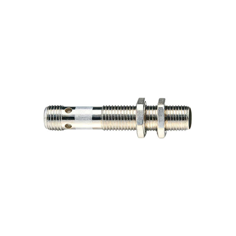
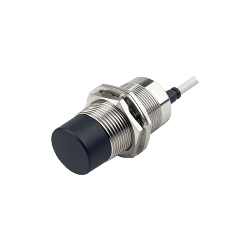
- Pot Cores: Offer excellent magnetic shielding and high sensitivity by effectively containing the flux. They are often used in shielded (flush-mountable) sensor designs.
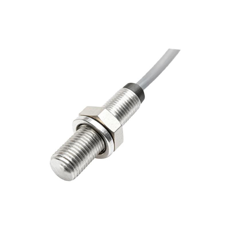
- Rod Cores (Slug Cores): Simple cylindrical shapes that project flux further, typically used in non-shielded (non-flush) sensors which offer longer sensing distances but are more susceptible to lateral interference.
- E-Cores and U-Cores: Used in more complex designs, sometimes for differential or specialized sensors.
The core's physical dimensions—length, cross-sectional area, and the presence of an air gap—are carefully calculated. A larger cross-sectional area reduces flux density, helping avoid saturation. The length and shape influence the field's projection. An air gap, sometimes intentionally introduced, can linearize certain characteristics or adjust the effective permeability, though it generally reduces overall sensitivity.
Performance optimization involves balancing multiple, often competing, factors. To maximize the nominal sensing distance (Sn), engineers aim for high-permeability materials and core geometries that project flux effectively. However, this must be balanced against the need for a stable temperature coefficient and resistance to saturation from strong target materials or high currents. For switching frequency (repeat accuracy), a core with low losses and a design that ensures a sharp, well-defined magnetic field boundary is essential. Miniaturization trends push for cores made from high-frequency NiZn ferrites that can maintain performance in tiny form factors.
Furthermore, the core's interaction with the coil (number of turns, wire gauge) and the oscillator circuit is a system-level design task. The core-coil assembly forms a tuned circuit. The core material's properties directly affect the inductance (L) and quality factor (Q) of this circuit, which in turn determines the optimal operating frequency and signal-to-noise ratio.
In harsh industrial environments, the core must also be considered within the sensor's overall packaging. While the core itself is ceramic, it is often encapsulated with the coil in a resin within a metal or polymer housing. Mechanical stress on the housing should not transfer to the core, as stress can alter its magnetic properties (magnetostriction effect).
In conclusion, the magnetic core in an inductive proximity sensor is far from a passive component. It is a precisely engineered element whose material composition and physical design dictate the fundamental