In industrial automation and control systems, the reliable operation of sensors is paramount. Among the most widely used components are inductive proximity sensors, with the E2A series from Omron being a benchmark for durability and performance. However, even the most robust sensor is only as good as its installation, and the connection wiring is a critical, often underestimated, aspect. This guide delves into the essential principles, wiring configurations, and best practices for connecting E2A proximity sensor connection cables to ensure optimal system integrity and longevity.
Understanding the E2A sensor's electrical characteristics is the first step. These DC-powered sensors typically come in two output types: NPN (sinking) and PNP (sourcing). The connection cable, often an integral part of the sensor or a separate pigtail lead, usually consists of three core wires: brown (for DC positive supply, +V), blue (for DC common, 0V), and black (for the switched output signal). Some models may include an additional white wire for diagnostic or complementary output functions. It is absolutely crucial to consult the specific sensor's datasheet to confirm the wire color coding and pinout, as variations exist between models and manufacturers.
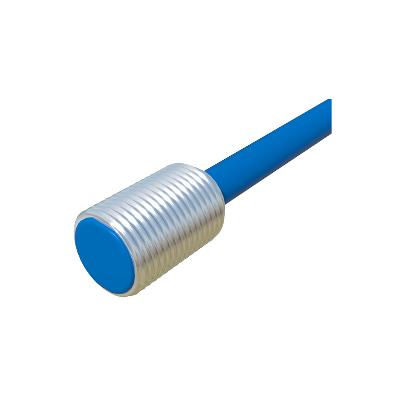
The standard wiring procedure involves connecting the brown wire to the positive terminal of your DC power supply (commonly 12-24V DC). The blue wire connects to the negative terminal or 0V common of the same supply. The black output wire is then connected to your load. For a PNP sensor, the load (e.g., a PLC input, relay coil, or indicator lamp) is connected between the black wire and the 0V common. When the sensor detects a target, it sources current from the +V supply through the black wire to the load. Conversely, for an NPN sensor, the load is connected between the black wire and the +V supply. Upon detection, the sensor sinks current from the load down to the 0V common.
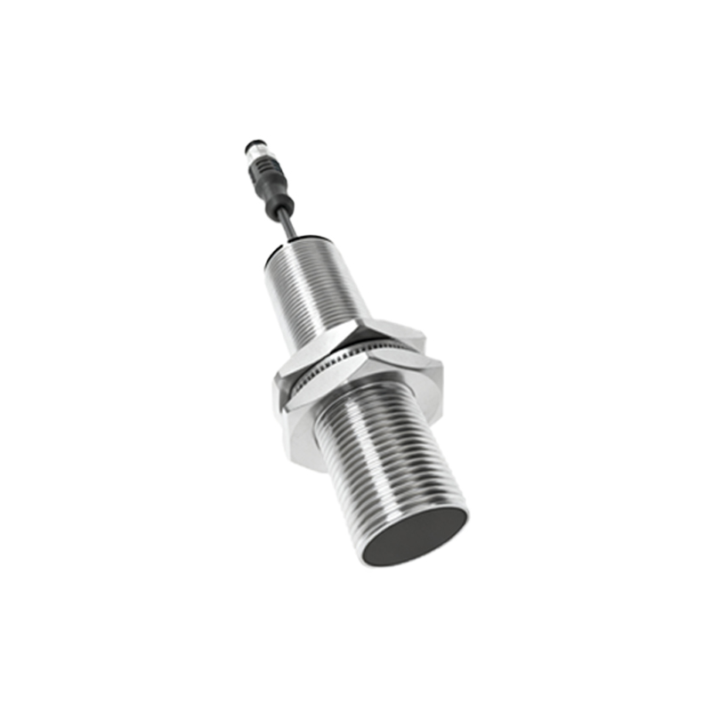
A fundamental and non-negotiable practice is implementing proper shielding and grounding for the connection cable, especially in environments with significant electromagnetic interference (EMI) from motors, drives, or welding equipment. The cable's shield, typically a braided or foil layer surrounding the conductors, must be grounded at one end only—preferably at the control panel side. This prevents ground loops and effectively drains noise away from the signal conductors. The shield should never be used as a current-carrying conductor.
Cable routing is another critical consideration. Sensor cables should be routed separately from high-voltage power lines and motor leads. A minimum separation distance of 20-30 cm is recommended. If crossing is unavoidable, ensure the cables cross at a 90-degree angle to minimize inductive coupling. Use cable trays or conduits to provide physical protection and organized segregation. For long cable runs, which can lead to voltage drop or increased susceptibility to noise, consider using a higher gauge wire or installing signal conditioners or repeaters.
Environmental protection of the connection point is vital. Many E2A sensors feature pre-molded cables or M8/M12 quick-disconnect connectors. When using connectors, ensure they have an appropriate IP (Ingress Protection) rating for the environment (e.g., IP67 for washdown areas). For sensors with cable leads, the point where the cable enters the sensor body is a potential weakness. Use proper strain relief, such as cable glands, to prevent tension from being transferred to the internal solder joints. Avoid sharp bends at the sensor entry point.
Finally, systematic testing and documentation complete the process. Before energizing the entire system, use a multimeter to check for short circuits and correct continuity. Verify the sensor's output by actuating it with a target and measuring the voltage on the black wire. Document all connections in wiring diagrams, noting sensor part numbers, cable types, and destination PLC input addresses. This documentation is invaluable for future troubleshooting and maintenance.
In conclusion, meticulous attention to E2A proximity sensor connection wiring is not merely a technical detail but a cornerstone of system reliability. Correctly identifying output types, implementing robust shielding, careful cable routing, and ensuring environmental sealing will prevent intermittent faults, sensor damage, and costly downtime. By adhering to these engineering best practices, you integrate the proven performance of the E2A sensor into a stable and resilient control network.