Proximity sensors are fundamental components in modern industrial automation, robotics, and safety systems. Their ability to detect the presence or absence of an object without physical contact makes them invaluable. This article delves into the electronic circuit diagrams of common proximity sensor types, providing a technical breakdown for engineers and designers.
The core principle behind most proximity sensors involves generating an electromagnetic field or a beam of radiation and detecting changes in that field caused by a target object. The electronic circuit is responsible for generating this signal, processing the return, and providing a usable output, typically a digital ON/OFF signal.
1. Inductive Proximity Sensor Circuit
Inductive sensors detect metallic objects. The primary circuit components include an oscillator, a demodulator, a trigger, and an output switch.
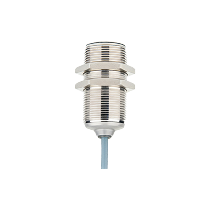
Oscillator: At the heart is an LC oscillator circuit (often a Colpitts or Hartley oscillator) that generates a high-frequency electromagnetic field from a coil (the sensor's active face). The coil forms the inductor (L), and capacitors (C) set the frequency, typically in the range of 100 kHz to 1 MHz.
Detection Circuit: When a metal object enters this oscillating field, eddy currents are induced in the target. This causes a power loss in the oscillator, leading to a decrease in the oscillation amplitude. This amplitude change is key.
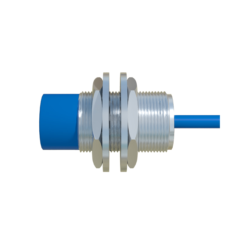
Demodulator & Trigger: The attenuated signal is rectified and smoothed (demodulated) to produce a DC voltage level. This level is fed into a comparator (the trigger stage), which compares it to a preset reference voltage. If the signal falls below the threshold, the comparator state changes.
Output Stage: The comparator's output drives a solid-state switch. For a 3-wire DC sensor, this is typically an NPN or PNP transistor. In a circuit diagram, you would see the transistor configured to sink (NPN) or source (PNP) current to the load (e.g., a PLC input). Protection components like flyback diodes (for inductive loads) and current-limiting resistors are integral parts of this stage.
2. Capacitive Proximity Sensor Circuit
Capacitive sensors can detect both metallic and non-metallic materials (plastics, liquids, wood). The circuit is conceptually similar to the inductive type but measures capacitance change.
Oscillator & Capacitive Plate: The circuit again uses an oscillator, but the frequency is determined by an RC or LC network where the sensor's active surface acts as one plate of a capacitor. The target object acts as the other plate (or alters the dielectric constant).
Capacitance Change Detection: As a target approaches, the effective capacitance increases. This change in capacitance shifts the oscillator's frequency or its ability to start oscillating.
Signal Processing: The circuit converts this frequency or amplitude shift into a DC voltage. This is achieved through a frequency-to-voltage converter (FVC) circuit or an amplitude detection circuit similar to the inductive sensor.
Comparator and Output: The resulting DC voltage is compared against a threshold by a comparator. The output stage is identical to that of an inductive sensor, providing a switched signal. A sensitivity adjustment potentiometer is commonly found in the reference voltage leg of the comparator.
3. Photoelectric (Diffuse) Proximity Sensor Circuit
These sensors use light, typically infrared (IR) or laser.
Emitter Circuit: A simple driver circuit, often using a constant current source, powers an IR Light Emitting Diode (LED). The LED is pulsed at a specific frequency (modulated) to make the sensor immune to ambient light.
Receiver Circuit: This is the critical part. A phototransistor or photodiode receives the reflected light from the target. The received signal is extremely weak.
Amplification and Filtering: The signal first passes through a high-gain, low-noise operational amplifier (op-amp) stage. Following this, a band-pass filter tuned to the emitter's modulation frequency rejects unwanted DC light (like sunlight) and noise.
Demodulation and Output: The filtered AC signal is demodulated (rectified and integrated) to produce a clean DC level proportional to the received light intensity. This level is fed to a comparator with adjustable sensitivity. The output stage is a standard transistor switch.
Key Design Considerations in Circuit Diagrams:
Power Supply Regulation: Most sensor ICs and oscillators require stable, low-noise voltage, necessitating onboard voltage regulators or filters.
Hysteresis: The comparator circuit almost always includes hysteresis (via positive feedback) to prevent output chatter when the target is at the exact detection threshold.
Protection Circuits: Diagrams include components for reverse polarity protection, overvoltage