Glass proximity sensors are critical components in a wide array of industrial and consumer applications, from automated manufacturing lines and packaging machinery to touchless faucets and elevator call buttons. Their primary function is to detect the presence or absence of an object without physical contact, typically using an infrared (IR) light beam. The "glass" refers to the protective lens covering the emitter and receiver elements. Ensuring these sensors operate correctly is paramount for system reliability, safety, and efficiency. This guide outlines a systematic approach for testing and troubleshooting glass proximity sensors.
Understanding the Operating Principle
Most common glass proximity sensors operate on the diffuse or reflective principle. The sensor contains an IR LED (emitter) and a phototransistor or photodiode (receiver). The emitter projects a beam of infrared light. When an object enters the detection zone, it reflects a portion of this light back to the receiver. The sensor's internal circuitry processes this signal change and triggers an output switch (typically PNP, NPN, or analog). Understanding this is key to testing; you are essentially verifying the integrity of this light path and signal conversion.
Pre-Test Preparations and Safety
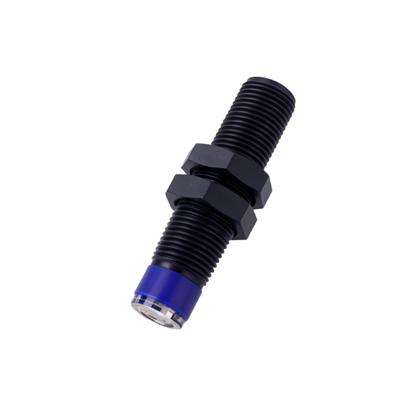
1. Power Down: Always disconnect power to the sensor and the associated control system before handling wiring or the sensor itself. Lock-out/Tag-out (LOTO) procedures should be followed in industrial settings.
2. Consult Documentation: Obtain the datasheet for the specific sensor model. Critical parameters include sensing distance, supply voltage (e.g., 10-30V DC), output type, and connection diagram.
3. Visual Inspection: Examine the glass lens for cracks, chips, or heavy contamination (dust, oil, paint). Even minor obstructions can severely attenuate the IR beam. Clean the lens gently with a soft, lint-free cloth and isopropyl alcohol if needed.
4. Environmental Check: Ensure the operating environment is within specifications. Factors like ambient light (strong sunlight can saturate the receiver), temperature extremes, and airborne particulates can affect performance.
Step-by-Step Testing Procedure
1. Basic Electrical and Output Test:
Reconnect power according to the wiring diagram. Using a digital multimeter (DMM):
Measure Supply Voltage: Check that voltage at the sensor's terminals matches the required level and is stable.
Test Output State: With no target present, measure the output voltage. For a DC sinking (NPN) sensor, the output should be near 0V (OFF). For a DC sourcing (PNP) sensor, the output should be near supply voltage (OFF). Now, introduce a standard target (as specified in the datasheet, usually a white matte card) at the nominal sensing distance. The output state should switch. For a PNP sensor, the output should drop to near 0V when an object is detected (ON). Verify this change with the DMM. Some sensors have an LED indicator that confirms this switch.
2. Functional Performance Test:
This test evaluates the actual sensing capability.
Response Test: Move a target in and out of the detection zone. The output should switch crisply and consistently. Use an oscilloscope to monitor the output signal if you suspect bounce or delay issues.
Sensing Distance Test: Gradually move a standard target toward the sensor lens until the output switches. Measure this distance. It should be within the tolerance of the rated nominal sensing distance. Repeat this several times to check for repeatability. A significant reduction in sensing range often points to a weakened emitter, dirty lens, or misalignment.
3. Oscilloscope Diagnostic Test (Advanced):
For persistent issues, an oscilloscope is invaluable. Probe the receiver's output pin before the internal comparator (this may require schematic knowledge). You will observe a small DC voltage. When a target reflects light back, this voltage should increase. A weak or no change indicates a problem with the emitter strength, receiver sensitivity, or reflectivity of the target. This test can isolate whether the issue is in the optical assembly or the subsequent electronic circuitry.
Common Troubleshooting Scenarios
Sensor Not Switching At All:
Cause: Incorrect wiring, dead power supply, internal failure.
Action: Double-check wiring against the datasheet. Verify power supply voltage and current capacity. Swap the sensor with a known-good unit if possible.
Intermittent or Unreliable Operation:
Cause: Unstable power supply, electrical noise, marginal sensing distance, environmental interference (vibration, steam, ambient light).
Action: Check for voltage dips or spikes. Ensure shielded cables are used and grounded properly. Increase the margin between the operating distance and the nominal sensing distance (