In industrial automation and control systems, proximity sensors are indispensable components for non-contact detection of objects. Among the various types, 4-wire DC proximity sensors are widely favored for their ability to provide both Normally Open (NO) and Normally Closed (NC) switching outputs from a single device. Correct wiring is paramount to ensure reliable operation, safety, and longevity of the sensor and the connected machinery. This guide provides a detailed, professional walkthrough for wiring a standard 4-wire DC proximity sensor.
First and foremost, safety is the highest priority. Before beginning any wiring procedure, ensure that all power sources to the control panel or cabinet are locked out and tagged out (LOTO). Verify the absence of voltage using a properly rated multimeter. Always consult the specific sensor's datasheet provided by the manufacturer, as color codes and pin configurations can vary between brands and models. The generic information provided here is based on common industry standards, typically following IEC or NAMUR guidelines.
A standard 4-wire DC proximity sensor will have four distinct wires, usually color-coded as follows:
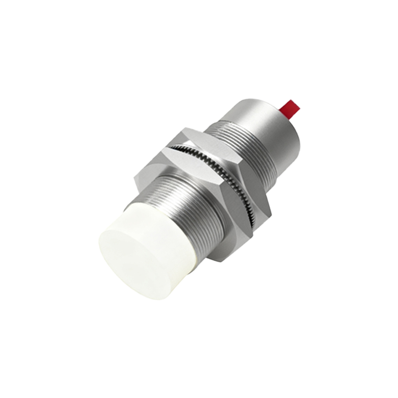
Brown Wire: This is the positive supply line (+V). It connects to the positive terminal of your DC power source.
Blue Wire: This is the negative supply line or common (0V). It connects to the negative terminal of your DC power source.
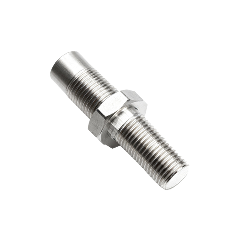
Black Wire: This is the Normally Open (NO) output signal wire. In the sensor's idle state (no target detected), this circuit is open. When a target enters the sensing range, this circuit closes, allowing current to flow to the load (e.g., a PLC input, relay coil, or indicator lamp).

White Wire: This is the Normally Closed (NC) output signal wire. Its operation is opposite to the black wire. In the idle state, this circuit is closed. When a target is detected, this circuit opens, interrupting the current flow.
The typical DC power supply range for these sensors is 10-30V DC. It is crucial to match the sensor's voltage rating with your power supply.
Step-by-Step Wiring Procedure:
1. Identify and Prepare: Identify the four wires according to the sensor's documentation. Prepare the wires by stripping a small amount of insulation from the end of each. Use ferrules for a secure and professional connection if your terminal blocks accept them.
2. Connect Power Supply Wires:
Connect the Brown wire to the positive (+) terminal of your DC power supply (e.g., 24V DC).
Connect the Blue wire to the negative (-) or common (0V) terminal of the same DC power supply.
Important: Ensure the power supply is rated for the sensor's current consumption and any potential inrush current. A small fuse (e.g., 2A) in line with the brown wire is a recommended practice for circuit protection.
3. Connect the Output Signal Wires: The output wires (Black and White) are switched lines that will control your load. They must be connected to the load, and the other side of the load must be connected to either the positive or negative side of the power supply, depending on the desired wiring configuration: PNP (sourcing) or NPN (sinking). Most 4-wire sensors are configured as two independent PNP outputs.
For a PNP (Sourcing) Configuration (Most Common):
The Black (NO) and White (NC) wires act as positive outputs.
Connect one side of your load (e.g., PLC digital input module designed for PNP, relay coil) to the desired output wire (Black for NO logic, White for NC logic).
Connect the other side of your load directly to the Blue wire (0V/negative) of the power supply.
In this setup, when activated, the sensor "sources" positive current to the load.
4. Verify Load Compatibility: Confirm that your load (PLC input, relay, etc.) is compatible with the sensor's output type (PNP), voltage, and current rating. The sensor datasheet will specify the maximum load current it can switch.
5. Testing and Commissioning: After double-checking all connections for tightness and correctness, carefully apply power. Use a non-metallic tool (like a plastic screwdriver) to bring a target of the correct material (usually ferrous or non-ferrous metal as specified) within the sensor's sensing range. Observe the load's behavior.
For a Black (NO) wire connection: The load should activate