In the world of automation and smart devices, proximity sensors work silently and invisibly. While their function is often abstract, proximity sensor images provide a tangible window into this essential technology. These visuals are more than just pictures; they are crucial tools for engineers, students, and enthusiasts to understand, select, and apply these sensors effectively.
A typical proximity sensor image reveals a compact, often cylindrical or rectangular housing. The front face usually contains the sensing element, which can appear as a clear lens for optical types or a flat metallic disc for inductive variants. High-resolution images might show intricate details like the emitter and receiver apertures in an infrared sensor, separated by a small barrier to prevent internal interference. For capacitive sensors, the image might highlight the active sensing surface. Scale is often provided, with a coin or ruler nearby, emphasizing their small size—frequently no larger than a fingertip.
Beyond the sensor itself, application photos are invaluable. One common image shows an inductive proximity sensor mounted on a metal bracket, its sensing face positioned precisely a few millimeters from a rotating gear. This visual immediately communicates its role in detecting the gear's teeth for speed or position monitoring. Another powerful image might depict an array of diffuse photoelectric sensors on a conveyor line, their red LED beams (often visible in photos) creating a grid that detects packages of varying heights and colors. These context-rich images bridge the gap between theory and real-world implementation.
Diagrams and cutaway illustrations form another critical category. A cross-sectional diagram of an ultrasonic proximity sensor, for instance, visually explains the principle. It clearly shows the piezoelectric transducer, the sound wave emission cone, and the path of the reflected wave. Annotated images that label key components—such as the oscillator coil in an inductive sensor or the timing circuitry in a digital output model—are particularly educational. They deconstruct the sensor's "black box," making complex electromagnetic or electro-optical interactions comprehensible.
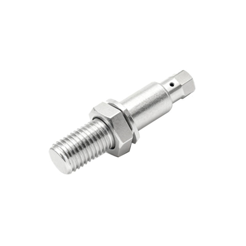
For troubleshooting and selection, comparison images are extremely useful. A side-by-side series might show the different sensing ranges of various models, or contrast the sensing fields of a standard inductive sensor versus one with an extended range. Images capturing a sensor's response to different target materials—like the clear detection of a metal screw versus the weak response to a plastic bottle—convey practical limitations instantly. Installation error photos, such as a sensor misaligned or mounted too close to a metal frame causing false triggers, serve as excellent visual guides for best practices.
The evolution of technology is also documented through these images. Early-generation sensors were bulky and wired, while modern images showcase miniaturized, chip-based sensors surface-mounted directly onto circuit boards inside smartphones. A striking image might compare a traditional 18mm cylindrical sensor to a modern M8 micro-sensor, highlighting decades of miniaturization. Furthermore, advanced graphics and 3D models generated for datasheets provide precise dimensional drawings and sensing field plots, essential for integration into CAD designs.
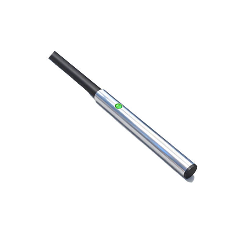
In summary, proximity sensor images serve multiple roles: as educational diagrams, application guides, selection aids, and historical records. They translate technical specifications into visual understanding, showing not just what the sensor is, but what it does and how it fits into the larger system. For anyone working with automation, these visuals are an indispensable resource, making the invisible world of detection and presence sensing vividly clear.