In industrial automation and control systems, proximity switches are indispensable components for detecting the presence or absence of objects without physical contact. Among them, normally open (NO) proximity sensors are widely used due to their reliable operation and straightforward integration. This article provides a comprehensive guide to the wiring diagram of a normally open proximity switch sensor, covering fundamental principles, terminal identifications, connection methods, and practical considerations for optimal performance.
A normally open proximity sensor operates on the principle of electromagnetic induction, capacitive sensing, or ultrasonic technology, depending on the type. For inductive sensors, which are common in metal detection applications, an oscillating circuit generates an electromagnetic field. When a metallic target enters this field, it causes a change in oscillation amplitude, triggering the sensor's output switch. In a normally open configuration, the output circuit remains open (non-conductive) when no target is detected. Upon sensing a target within its specified sensing range, the output circuit closes, allowing current to flow to the connected load, such as a PLC input, relay, or indicator lamp.
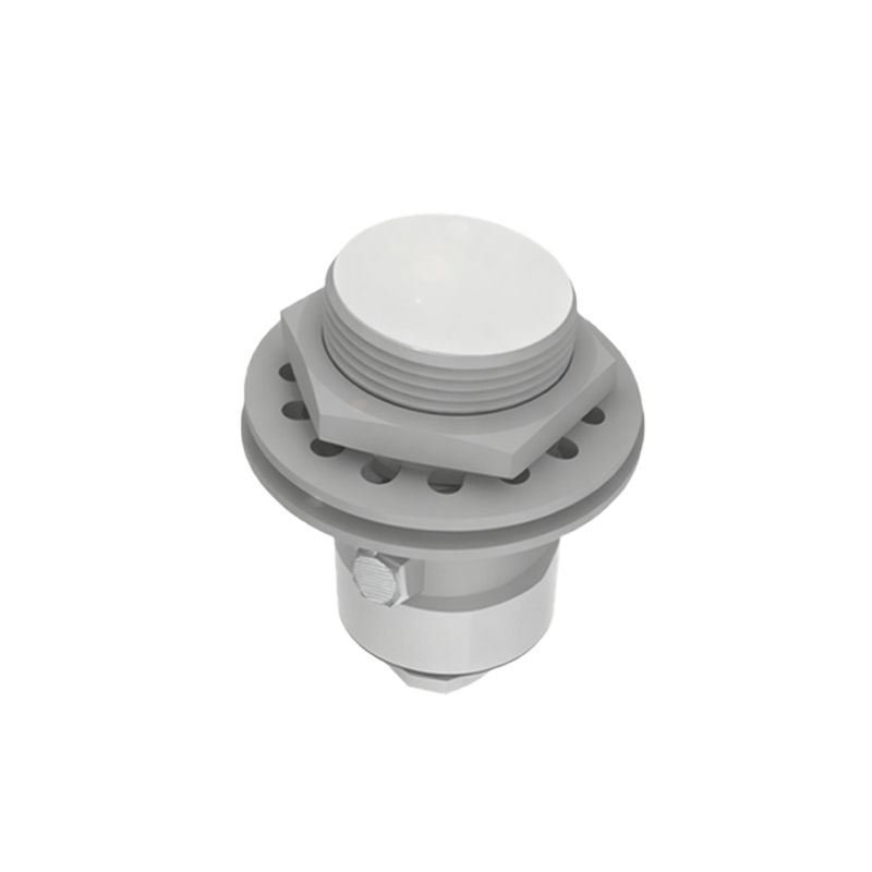
Understanding the wiring terminals is crucial for correct installation. Typically, a three-wire DC proximity sensor includes the following terminals:
- Brown wire: Connected to the positive DC supply voltage (e.g., +24V DC).
- Blue wire: Connected to the negative DC supply voltage or ground (0V).
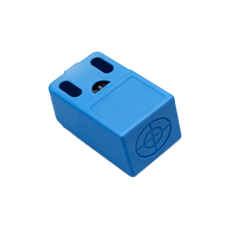
- Black wire: The output signal wire, which provides the switched output. In a normally open sensor, the black wire is internally connected to the positive supply through the switch; when activated, it connects to the load, completing the circuit.
For AC sensors, wiring may involve different color codes, such as brown for live, blue for neutral, and black for output. Always refer to the manufacturer's datasheet for specific terminal designations, as variations exist.
The basic wiring diagram for a normally open DC proximity sensor involves connecting the brown wire to the positive terminal of the power supply and the blue wire to the negative terminal. The black output wire is then connected to one terminal of the load (e.g., a relay coil), while the other terminal of the load is linked to the positive supply. This configuration ensures that when the sensor detects a target, the output closes, energizing the load. For instance, in a control panel, the sensor might be wired to a PLC digital input module, with the black wire connected to the input point and the common terminal of the PLC tied to the positive voltage.
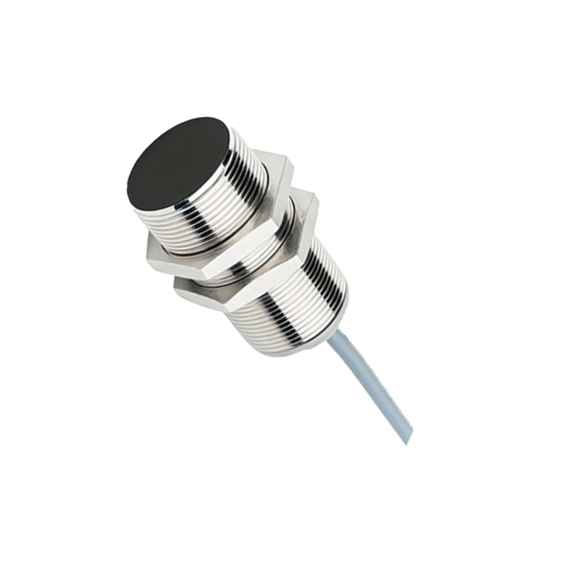
Shielded cables are recommended for wiring to minimize electromagnetic interference, especially in environments with high noise from motors or frequency drives. The cable shield should be grounded at one end only, typically at the control cabinet, to prevent ground loops. Additionally, ensure proper wire sizing according to the sensor's current rating—usually up to 200mA for standard models—to avoid voltage drops or overheating.
Practical installation tips include mounting the sensor securely to avoid vibration-induced false triggers and maintaining the specified sensing distance, which varies by sensor type (e.g., 2mm to 15mm for inductive models). Avoid placing metallic objects near the sensor face that could cause interference. For wiring longevity, use conduit or cable ducts in harsh industrial settings to protect against moisture, dust, and mechanical damage.
Testing the wiring is straightforward: apply power to the sensor and observe its indicator LED. When no target is present, the LED may be off or steady, indicating the open state. Bringing a target within range should activate the LED and close the output, which can be verified with a multimeter measuring continuity between the black and brown wires or by checking the load operation. If issues arise, such as the sensor not triggering, double-check connections, power supply polarity, and load compatibility.
In summary, wiring a normally open proximity switch sensor involves a simple yet precise process. By adhering to standard color codes, following manufacturer guidelines, and considering environmental factors, engineers can ensure reliable sensor performance in diverse applications, from conveyor systems to robotic arms. This guide serves as a foundational reference for professionals seeking to implement these sensors effectively in their automation projects.