Laser distance measurement sensors have become indispensable tools across numerous industries, from industrial automation and robotics to construction and surveying. At the heart of these precise instruments lies a sophisticated electronic circuit that orchestrates the emission, reception, and interpretation of laser light. This article delves into the core circuit design principles and implementation strategies for building a reliable and accurate laser rangefinder.
The fundamental operating principle is Time-of-Flight (ToF). A pulsed laser diode emits a short, high-intensity burst of light towards a target. The light reflects off the target and returns to a photodetector, typically an avalanche photodiode (APD) or a PIN photodiode. The circuit's primary challenge is to measure the incredibly short time interval between the emission and reception of this pulse with nanosecond or even picosecond precision.
The circuit architecture can be broadly segmented into several key functional blocks:
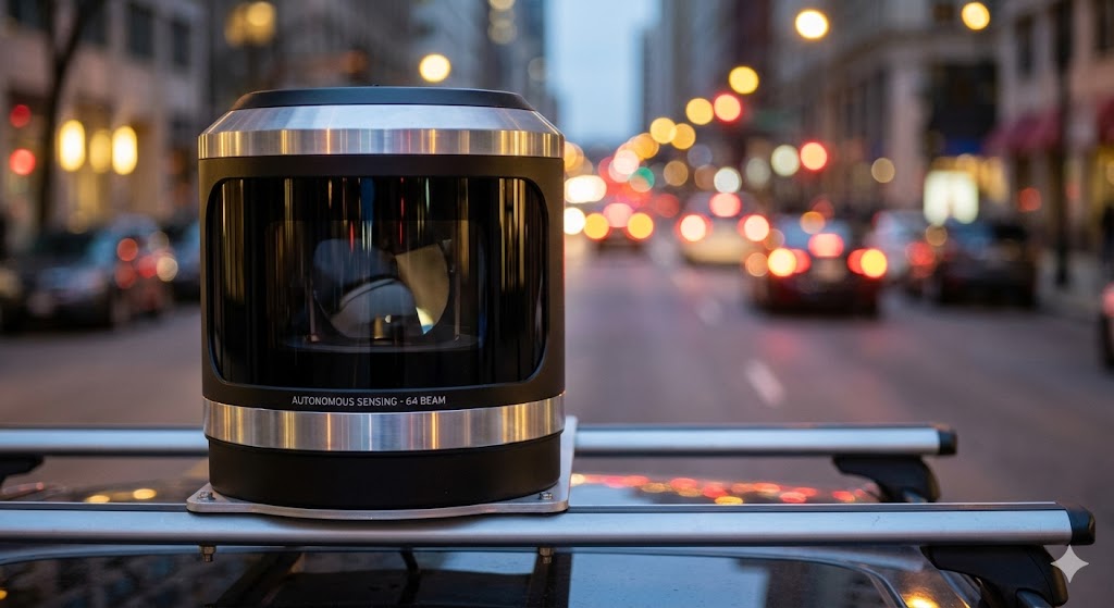
1. Laser Driver Circuit: This is a critical and demanding section. It must generate high-current, short-duration pulses to drive the laser diode. A common approach uses a MOSFET switch controlled by a precision pulse generator. The driver must ensure fast rise and fall times for the optical pulse to achieve high resolution. Careful layout is paramount to minimize parasitic inductance, which can distort the pulse shape. Protection circuits, such as current limiting and transient voltage suppressors, are essential to safeguard the sensitive laser diode from overcurrent and electrostatic discharge (ESD).
2. Optical Receiver Front-End: The returning optical signal is extremely weak. The photodetector converts the faint light pulse into a minuscule electrical current. The subsequent transimpedance amplifier (TIA) is the workhorse of the receiver, converting this current into a usable voltage signal. Designing the TIA involves a careful trade-off between bandwidth, gain, and noise. A high bandwidth is needed to preserve the fast pulse, but this often increases noise. Low-noise operational amplifiers and careful selection of the feedback resistor and capacitor are crucial. For very weak signals, an APD biased near its breakdown voltage offers internal gain, but this requires a stable, high-voltage bias supply.
3. Timing Measurement Circuit: This is the precision clock of the system. For moderate accuracy (centimeter-level), a method using a Time-to-Digital Converter (TDC) integrated circuit is prevalent. The TDC measures the time interval between the "start" signal (synchronized with laser emission) and the "stop" signal (from the receiver's comparator output). High-end systems may use the "time-stretching" technique or high-speed analog-to-digital converters (ADCs) with digital signal processing (DSP) to achieve sub-millimeter accuracy. The stability of the system's master clock oscillator directly impacts measurement stability.

4. Signal Processing and Control Unit: A microcontroller (MCU) or a field-programmable gate array (FPGA) acts as the system's brain. It triggers the laser pulse, reads the time interval from the TDC, performs calculations (distance = (speed of light * time) / 2), and manages interfaces (e.g., UART, I2C, USB). It also implements filtering algorithms to reject ambient light noise and false triggers. An FPGA can offer superior performance for high-speed, deterministic control of the timing sequence.
5. Power Management: The circuit often requires multiple regulated voltage rails: a low-voltage supply for digital logic (3.3V, 5V), a medium-voltage supply for analog circuits and laser driver (often 12V), and potentially a very high-voltage, low-noise supply for an APD (100V+). Efficient switching regulators are used where possible, but linear regulators may be necessary for noise-sensitive analog sections. Proper decoupling and grounding strategies are non-negotiable for stable operation.
Implementation Challenges and Considerations:
* Noise Mitigation: Electrical noise from the laser driver, switching power supplies, and digital circuits can easily swamp the tiny received signal. Strategic use of shielding, separate ground planes for analog and digital sections, and extensive filtering are mandatory.
* Ambient Light Rejection: Sunlight or strong artificial light can saturate the receiver. Optical bandpass filters centered on the laser's wavelength (commonly 905nm or 1550nm) are used. Electrical techniques include AC-coupling the TIA and using pulsed operation with synchronous detection.
* Temperature Compensation: The performance of laser diodes and photodiodes varies with temperature. Incorporating temperature sensors and implementing compensation algorithms in the MCU firmware is essential for maintaining accuracy over a wide operating range.
* Eye Safety: For lasers operating in the visible or near-infrared spectrum, circuit designs must incorporate hardware interlocks and current limits to ensure compliance with laser safety classes (e.g., IEC 60825-1 Class 1 or Class 2).
In conclusion, designing a laser distance sensor circuit is a multidisciplinary endeavor blending high-speed analog design, precision timing, digital control, and optoelectronics. A successful design hinges on a deep understanding of each functional block and their interactions, with meticulous attention paid to noise control, signal integrity, and thermal management. As integrated circuits like highly integrated ToF sensors become more advanced, they simplify design efforts, but the fundamental principles of robust circuit design remain the cornerstone of achieving high performance and reliability in the field.