As an experienced electrical engineer specializing in industrial automation, I often encounter scenarios where technicians need to verify the functionality of proximity sensors or simulate their operation within a control circuit. One common method involves creating a temporary short-circuit across the sensor's output terminals. It is crucial to understand that this procedure is strictly for diagnostic and testing purposes under controlled conditions. Performing this incorrectly can damage the sensor, the connected programmable logic controller (PLC), or other downstream equipment.
First, let's clarify the fundamental types of proximity sensors relevant to this discussion. The two primary categories are PNP (sourcing) and NPN (sinking) DC sensors. A PNP sensor switches the positive voltage to the load, while an NNP sensor switches the negative or ground path. Three-wire sensors typically have wires for power supply positive (brown), power supply negative (blue), and the switched output signal (black). The short-circuiting technique primarily concerns the output signal wire in relation to the power supply wires.
Safety and Preparatory Steps:
1. De-energize the Circuit: Always disconnect the main power supply to the sensor and the associated control panel. Lock Out and Tag Out (LOTO) procedures must be followed.

2. Identify the Sensor Type: Consult the sensor's datasheet or nameplate to confirm whether it is PNP or NNP and its voltage rating (e.g., 10-30V DC).
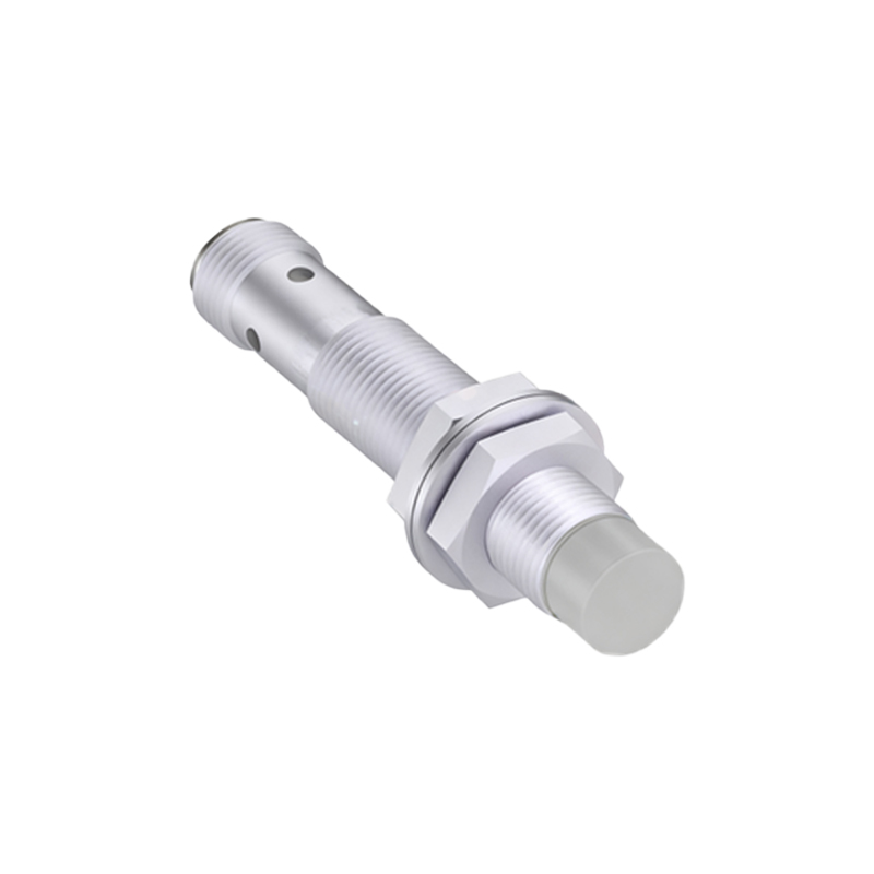
3. Locate the Wiring: Trace the sensor's cables back to the terminal block or interface module. Clearly identify the Brown (+V), Blue (0V/Common), and Black (Output) wires.
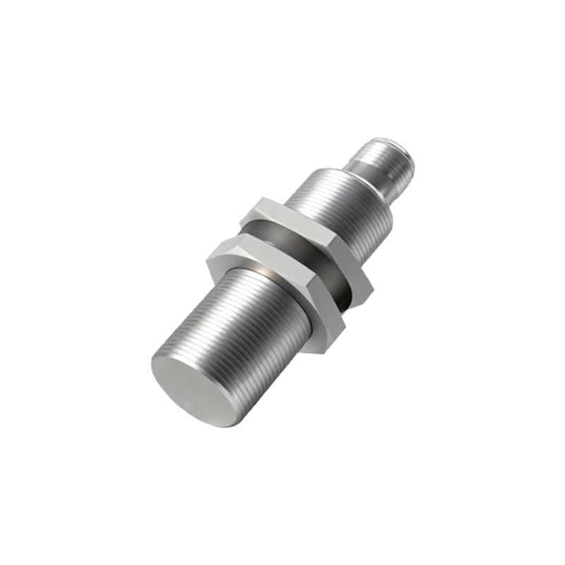
4. Gather Tools: You will need insulated jumper wires with alligator clips or a small, insulated screwdriver for terminal blocks, and a digital multimeter (DMM).
Procedure for Creating a Diagnostic Short-Circuit:
The goal is to manually mimic the sensor's "active" state by connecting its output terminal to either the positive or negative supply, depending on the sensor type. This bypasses the sensor's internal switching element.
For a PNP Sensor: To simulate the sensor detecting a target (output ON), you need to connect the sensor's output signal wire (Black) to the positive supply wire (Brown). This creates a path for current to flow from the sensor's output to the load, effectively "shorting" the output to +V. In a de-energized state for planning, you would place a jumper wire between the terminal for the Brown wire and the terminal for the Black wire at the controller's terminal block.
For an NPN Sensor: To simulate the output ON state, you need to connect the sensor's output signal wire (Black) to the negative or common supply wire (Blue). This creates a path to ground. In a de-energized state, you would place a jumper wire between the terminal for the Blue wire and the terminal for the Black wire.
Testing Sequence:
1. After installing the appropriate jumper wire based on the sensor type, re-energize the system cautiously.
2. Observe the indicator on the PLC input module or the status in the control software. For a PNP sensor shorted as described, the corresponding PLC input should energize (indicating a "High" or "1" signal). For an NPN sensor, the input should also energize (completing the circuit to common).
3. This confirms that the wiring from the terminal block to the PLC is functional and that the PLC input is working correctly. It isolates faults to the sensor itself or its power supply.
Critical Warnings and Misconceptions:
Never short the power supply wires (+V to 0V) directly. This is a catastrophic dead short across the power supply and will trip a fuse, damage the supply, or cause a fire hazard.
Never short the output of a powered sensor directly to the opposite supply rail (e.g., shorting a PNP output to negative without a load). While some sensors have short-circuit protection, this can stress or destroy the sensor's output transistor.
The method described here is a controlled diagnostic short across the sensor's internal switch, not a direct power supply short. It uses the existing load (the PLC input) to limit current.
This test does not verify the sensor's sensing capability. It only tests the electrical path. A functional test with a metal target is still required for full validation.
Alternative and Safer Methods:
For frequent testing, consider building a dedicated test fixture with a switch that toggles between the sensor signal and a manual override via a resistor to limit inrush current. Alternatively, using a programmable logic controller