Proximity sensors are fundamental components in modern industrial automation, playing a critical role in object detection, position sensing, and machine safety. Understanding their internal construction is invaluable for troubleshooting, repair, and gaining deeper insight into their operational principles. This guide provides a systematic, engineer-focused methodology for the safe and effective disassembly of a typical inductive proximity sensor. It is imperative to note that disassembly may void warranties and should only be performed by qualified personnel with appropriate safety training. Always disconnect and lock out all power sources before handling any electrical component.
Pre-Disassembly Preparations and Safety
Prior to any physical interaction, comprehensive preparation is essential. Begin by consulting the sensor's datasheet and technical manual from the manufacturer. Identify the specific model, its rated voltage, output type (PNP/NPN, NO/NC), and any special construction notes, such as weld-field immunity or extended temperature range designs. Gather the necessary tools: precision screwdrivers (commonly Torx or Phillips), needle-nose pliers, a digital multimeter, an anti-static wrist strap, and a clean, well-lit workspace with non-conductive surfaces. Don the anti-static strap to prevent damage to sensitive electronic components from electrostatic discharge (ESD). Visually inspect the sensor housing for signs of damage, cracks, or chemical exposure. Document the sensor's condition and connection wiring with photographs for accurate reassembly.
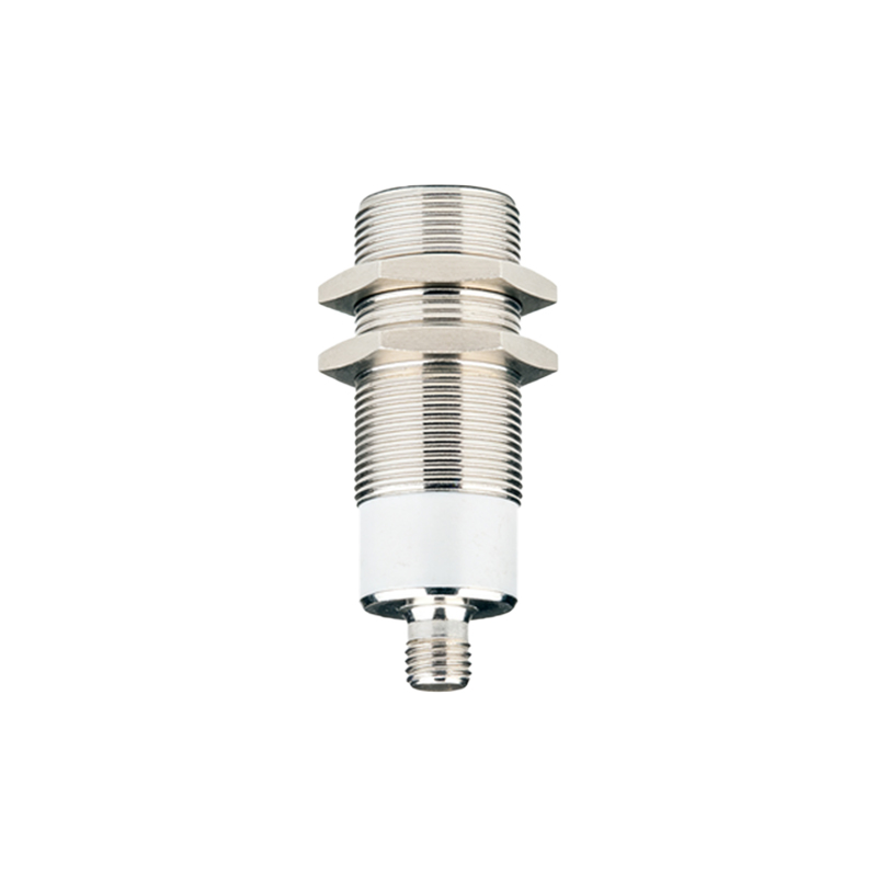
Housing Separation and Internal Access
The external housing of a proximity sensor is typically a cylindrical metallic barrel (often stainless steel or nickel-plated brass) with a molded plastic face and a threaded body. The sensing face is usually a non-metallic material like PBT or POM to allow electromagnetic field penetration. The first step is to remove the mounting nut and any locking rings. Carefully examine the junction between the barrel and the rear potting compound or plastic cap. This seal is critical for the sensor's IP (Ingress Protection) rating. For many models, the rear cap is ultrasonically welded or glued. Gentle, controlled prying with a flat-head screwdriver at designated seams may be required. Avoid using excessive force to prevent permanent housing deformation. Some industrial-grade sensors feature a screw-on rear cap or a bayonet-style locking mechanism.
Core Component Examination
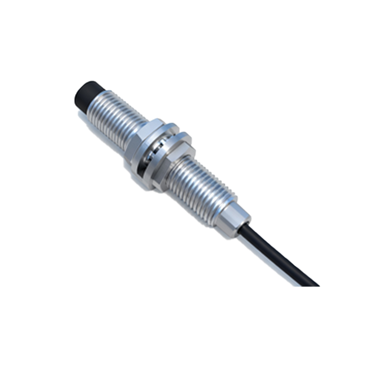
Once the housing is opened, the internal assembly is revealed. The core consists of four primary subsystems:
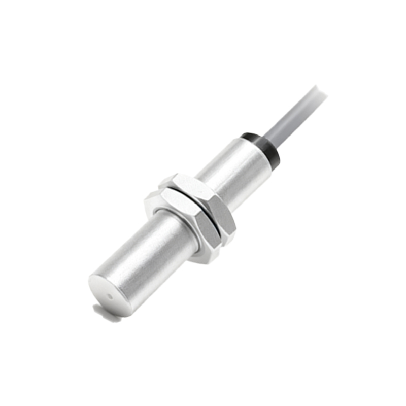
1. The Oscillator Coil and Ferrite Core: Located directly behind the sensing face, this is the heart of an inductive proximity sensor. A coil of fine wire is wound around a ferrite core, creating an oscillating electromagnetic field. Observe its placement and any shielding.
2. The Electronic Circuit Board: A small printed circuit board (PCB) hosts the oscillator circuit, demodulator, trigger, and output switching stage. The output transistor (for switching) and any application-specific integrated circuits (ASICs) or microcontrollers will be visible. Note the use of conformal coating, a protective lacquer-like layer that guards against moisture, dust, and chemical contaminants.
3. The Potting Compound: A dense, epoxy-based material encapsulates the PCB and coil assembly. This compound provides mechanical stability, vibration damping, thermal management, and enhances the IP rating. Removing this compound is destructive and generally irreversible. For analysis, careful drilling or chemical dissolution (with appropriate safety measures) may be used, but this terminates the component's functional life.
4. Cable Gland or Connector Interface: The point where the electrical cable or quick-disconnect plug interfaces with the internal PCB. Inspect the strain relief and the quality of solder joints.
Analysis and Diagnostic Points During Disassembly
During the disassembly process, an engineer can perform diagnostic checks. Before separating the PCB, use the digital multimeter to check for continuity in the coil windings. An open circuit indicates a broken coil, a common failure mode. Visually inspect the PCB for burnt components, cracked solder joints, or signs of corrosion from moisture ingress. Check the large capacitor in the power supply section for bulging or leakage. The condition of the potting compound can also be diagnostic; cracks or separation from components suggest exposure to thermal cycling or physical stress.
Reassembly Considerations and Final Notes
Reassembly is often more challenging than disassembly, especially if seals are compromised. If the potting compound was disturbed, the sensor's environmental ratings cannot be restored without specialized re-potting equipment. Ensure any O-rings or gaskets are correctly seated. The alignment of the sensing coil to the front face is critical for maintaining the rated sensing distance. If the housing was forcibly opened, achieving the original IP67 or IP69K rating is unlikely. The primary goal of such a teardown is forensic analysis for failure investigation, design benchmarking, or educational understanding, not for field repair. For operational systems,