In the realm of industrial automation and electrical control systems, proximity sensors are indispensable components for non-contact detection of objects. A fundamental aspect of their specification and wiring, often a point of confusion for both novices and seasoned professionals, is the concept of "Normally Open" (NO) and "Normally Closed" (NC) contacts. This distinction is not about the physical state of the sensor itself when powered, but rather defines the electrical state of its output switching element in its non-actuated, or "normal," condition. Understanding this principle is critical for designing safe, reliable, and logically correct control circuits.
First, let's establish the core definitions. The "normal" state refers to the condition of the sensor's output when it is powered on but not detecting a target within its specified sensing range. It is a resting, non-actuated state.
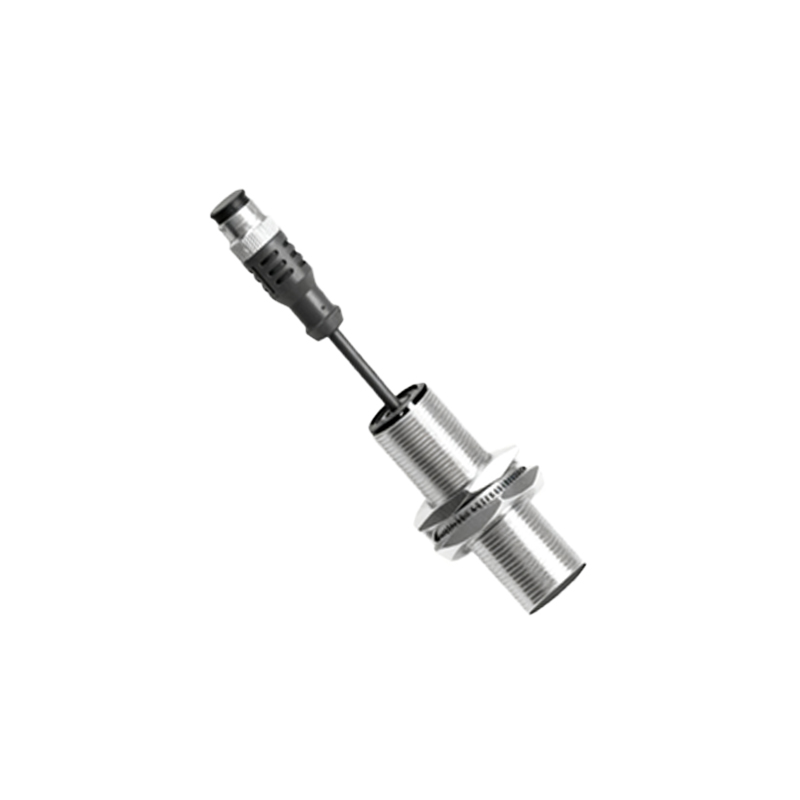
A Normally Open (NO) proximity sensor has an output circuit that is open (i.e., high impedance, no current flow) in its normal state. When a target enters the sensing field, the output switch closes, completing the circuit and allowing current to flow. In essence, the sensor "makes" the connection upon detection. This is the most common configuration. For a 3-wire DC sensor (typically brown wire to +V, blue wire to 0V/common), the black output wire acts as an NO contact. Voltage appears on the output wire only when a target is detected.
A Normally Closed (NC) proximity sensor operates inversely. Its output circuit is closed (i.e., low impedance, current can flow) in its normal, non-actuated state. When a target is detected, the output switch opens, breaking the circuit and stopping current flow. The sensor "breaks" the connection upon detection. Using the same 3-wire DC example, the black wire would act as an NC contact. Voltage is present on the output wire until a target is sensed, at which point it drops to near zero.
The choice between NO and NC is far from arbitrary; it is a deliberate design decision with significant implications for system safety, logic, and diagnostics.
Safety Considerations (Fail-Safe Design):
This is the paramount concern. In many critical applications, the failure mode of the sensor must be considered. An NC configuration is often employed in safety-related or monitoring circuits because it is inherently "fail-safe" for certain fault conditions. For instance, consider a sensor monitoring a guard door. If an NC sensor is used, its normal closed state keeps a safety circuit enabled. If the door opens (actuating the sensor), the circuit opens, triggering a stop. Crucially, if the sensor's wiring is cut or it loses power, the circuit also opens, simulating an "actuated" state and triggering a safe shutdown. An NO sensor in the same scenario would fail dangerously: a wire break would not change its output state, leaving the system unaware of the fault. This principle is central to standards like IEC 61508 for functional safety.
Control Logic and Circuit Design:
The selection directly influences the ladder logic or relay logic of a Programmable Logic Controller (PLC). An NO sensor contact in a ladder rung behaves like a normally open instruction; it becomes "true" or "closed" when activated. An NC sensor maps to a normally closed instruction in the logic, which is "true" when the sensor is not activated and becomes "false" or "open" when it is. Choosing the wrong type can invert the intended logic, leading to malfunctions. Engineers often choose the configuration that results in the simplest and most intuitive logic, minimizing the use of logical inverters (NOT functions).
Diagnostics and Status Indication:
NC contacts can provide inherent diagnostic information. In a system where a sensor should normally "see" a target (e.g., a motor shaft position), an NC sensor (which would be actuated, thus open) that develops a fault or loses its target will close its output. This change of state can be easily monitored to alert operators to a process deviation or sensor failure before it causes a product defect.
Wiring and Sourcing/Sinking:
It is vital to remember that NO/NC describes the switching action, which is independent of the sensor being a PNP (sourcing) or NPN (sinking) type. A PNP sensor switches a positive voltage to the load, while an NPN switches the ground path. You can have PNP-NO, PNP-NC, NPN-NO, and NPN-NC variants. The data sheet is the ultimate reference. For 2-wire AC/DC sensors, the NO/NC function is built into the device, and they wire in series with the load, much like