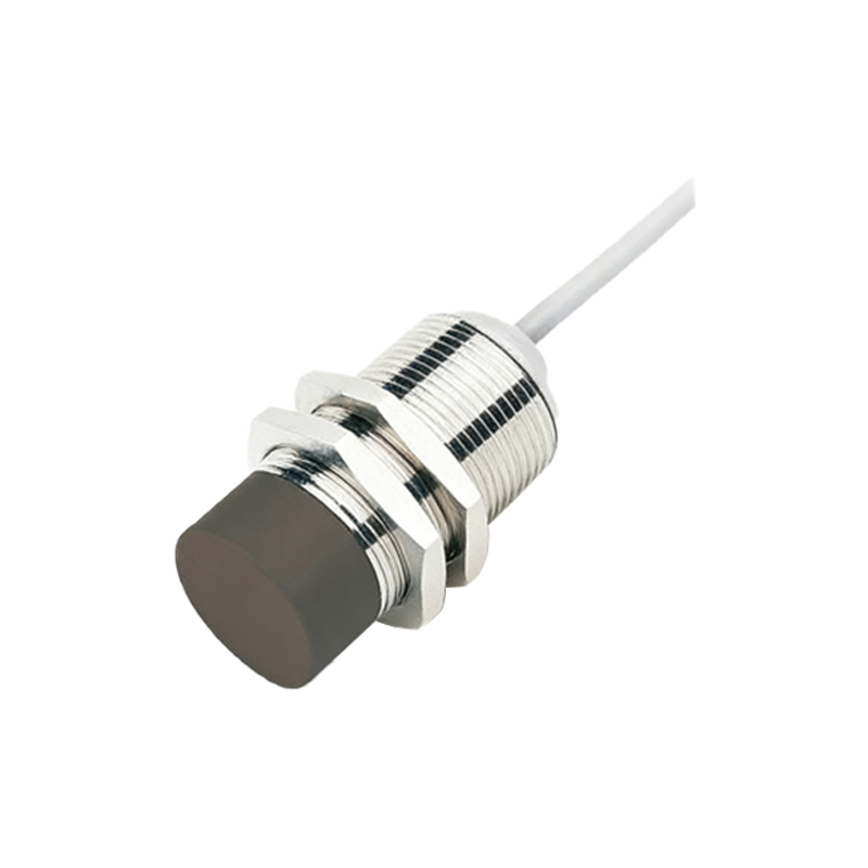
In the realm of industrial automation and machine safety, proximity sensors play a pivotal role in non-contact detection of metallic objects. Among the various types, flush-mountable proximity sensors are particularly valued for their ability to be installed without a gap, allowing them to be embedded directly into metal mounting surfaces without risk of interference from surrounding materials. This article delves into the schematic diagram of a typical inductive flush-mountable proximity sensor, explaining its core components and operational principles to provide a clear technical understanding.
At the heart of an inductive flush-mountable proximity sensor lies an oscillator circuit, a detection circuit, and an output stage, all meticulously integrated into a compact housing. The schematic diagram visually represents these electrical components and their interconnections. The oscillator, often a Colpitts or Hartley type, generates a high-frequency electromagnetic field that radiates from the active face of the sensor. This field is generated by a coil (L1) forming part of an LC tank circuit, connected to an oscillator IC or transistor network (Q1, R1, C1, C2). The frequency typically ranges from 100 kHz to 1 MHz. In a flush-mount design, a metal shield surrounds the coil, confining the magnetic field to the front face. This shielding is crucial and is represented in the schematic as a grounded Faraday shield or a specific core geometry notation, preventing the sensor from detecting lateral metallic objects and enabling its flush installation.
When a ferrous or non-ferrous metal target enters the sensing range, eddy currents are induced on the target's surface. These currents draw energy from the oscillator's electromagnetic field, causing a measurable change in the circuit. In the schematic, this is depicted as a loading effect on the LC tank, leading to a decrease in the oscillation amplitude. The detection circuit, which could be a peak detector or an amplitude demodulator (involving diodes D1, capacitor C3, and resistor R2), converts this amplitude change into a DC voltage signal. This signal is then fed into a comparator circuit (IC1, such as an LM311). The comparator compares the signal against a preset reference voltage (Vref, set by potentiometer R3). When the signal drops below the threshold—indicating a target is present—the comparator's output state changes.
The output stage of the sensor is responsible for switching an external load. Common output types include NPN (sinking), PNP (sourcing), or analog (4-20 mA / 0-10V). In a standard NPN DC three-wire schematic, the output transistor (Q2, often a MOSFET for switching speed and durability) is connected between the output wire (usually black) and the negative supply (0V/Common). The load (e.g., a PLC input or relay coil) is connected between the positive supply (V+, typically 10-30V DC, brown wire) and the output terminal. When the comparator triggers, it drives the gate of Q2, turning it on and completing the circuit to ground, thus "sinking" current and signaling a detection event. The schematic also includes essential protection components: a freewheeling diode (D2) across the load for inductive kickback protection, a zener diode (Z1) for voltage regulation/suppression, and filtering capacitors (C4, C5) for power supply decoupling.
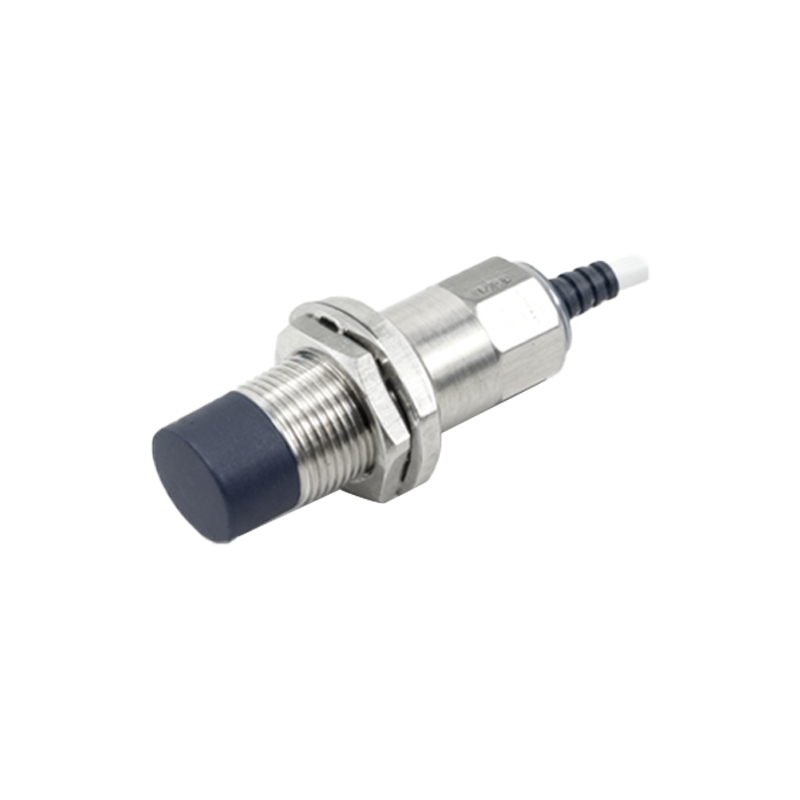
Understanding the schematic reveals key performance aspects. The sensing range is determined by the oscillator's power, coil design, and the detection circuit's sensitivity, all tunable via component values (e.g., R3 for hysteresis adjustment). The schematic also shows the connection for the LED status indicator (LED1 with current-limiting resistor R4), which provides visual feedback. A critical note for flush-mount sensors is the "null" or "shielding" effect represented in the coil's symbolic layout; it shows how the magnetic field lines are directed forward, unlike unshielded sensors whose fields extend laterally. This design minimizes blind zones and ensures reliable detection only from the front.
In summary, the schematic diagram of a flush-mountable proximity sensor is a blueprint of its intelligent design. It integrates oscillation, detection, comparison, and output switching into a robust package. For engineers, interpreting this schematic is fundamental for proper selection, integration into control systems (like connecting to a PLC input module), troubleshooting fault conditions such as false triggers or no output, and appreciating the design considerations that enable reliable operation in harsh industrial environments with vibration, temperature variations, and electromagnetic interference. Mastery of this diagram ensures optimal implementation of these versatile sensors in automated machinery, material handling, and safety systems.