Embedded proximity switch sensors represent a critical component in modern industrial automation, offering non-contact detection capabilities for various applications. These sensors are designed to be mounted flush with surrounding surfaces, providing a streamlined and protected installation suitable for harsh environments. The visual characteristics of embedded proximity sensors reveal important technical details that engineers must consider during selection and implementation.
Examining images of embedded proximity switches, several key design features become apparent. The housing typically exhibits a cylindrical or rectangular form factor with threaded metal bodies, often constructed from stainless steel or nickel-plated brass to withstand mechanical stress and corrosive conditions. The sensing face, usually made of polymer or ceramic material, appears flat and seamless with the housing, allowing for flush mounting without protruding elements. This design prevents material accumulation and reduces the risk of damage from passing objects.
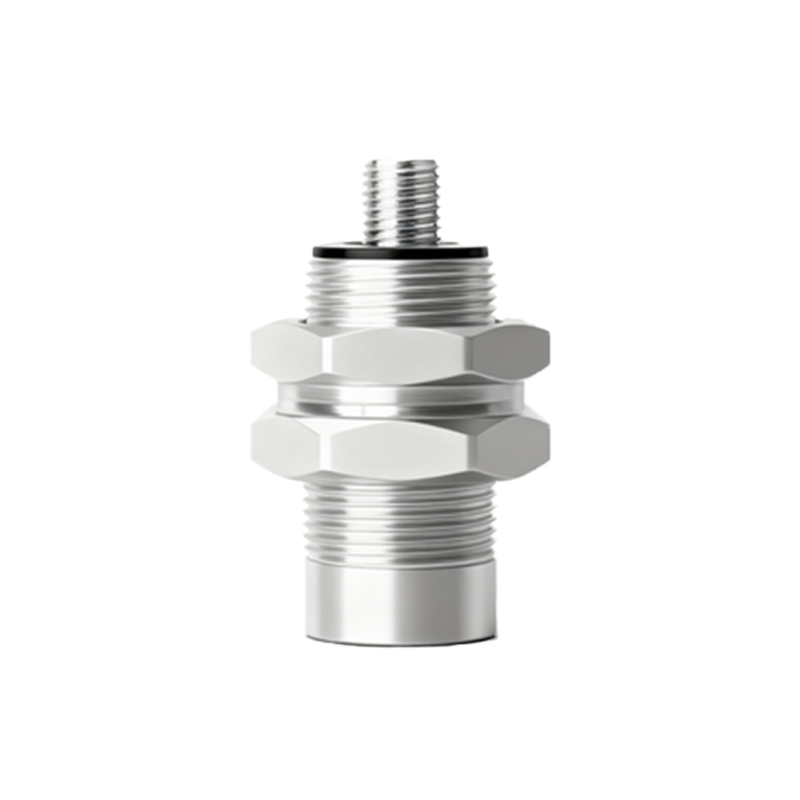
Electrical connections visible in product images demonstrate various interface options. Many embedded proximity sensors feature integrated cables with PUR or PVC insulation, while others show connector systems such as M8 or M12 quick-disconnect couplings. The cable exit direction—axial, radial, or at specific angles—affects installation flexibility in space-constrained applications. LED indicators, often visible as small colored dots near the sensing face or connection area, provide visual status feedback for operational monitoring and troubleshooting.
Technical diagrams accompanying product photographs reveal internal construction details. Cross-sectional views typically show the oscillator coil, amplifier circuit, and output switching elements arranged compactly within the housing. The sensing distance, indicated in specification sheets and often marked on product labels, varies according to sensor size and technology—inductive sensors typically offer ranges from 1 to 40 mm, while capacitive versions may detect non-metallic materials at shorter distances.
Installation images demonstrate proper mounting techniques, showing sensors recessed into machine frames or conveyor structures with precise alignment to target objects. Clearance requirements around the sensing face, visible in dimensional drawings, ensure reliable operation by preventing interference from adjacent metal surfaces. Images depicting sensing principles illustrate how electromagnetic fields or capacitive coupling interact with target materials, helping engineers understand detection limitations for various substances.
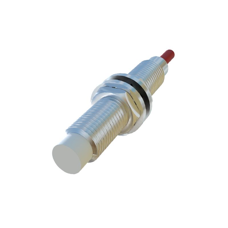
Application photographs showcase embedded proximity sensors in real-world scenarios: detecting piston positions in hydraulic cylinders, monitoring fill levels through container walls, counting packages on high-speed conveyors, or ensuring safety door closure in robotic cells. These visuals highlight environmental considerations such as IP67/IP69K protection ratings, temperature tolerance markings, and compatibility with cleaning processes in food or pharmaceutical industries.
Performance graphs included in technical documentation display response time characteristics, temperature drift compensation, and switching frequency capabilities. Visual comparisons between different sensor technologies—inductive, capacitive, ultrasonic, or magnetic—help engineers select appropriate solutions based on target material composition, required precision, and environmental factors.
Maintenance-related images demonstrate diagnostic procedures, showing how to interpret LED flashing patterns or use oscilloscope connections to verify signal integrity. Exploded-view diagrams illustrate component replacement procedures for field-repairable models, while other images highlight hermetically sealed designs intended for maintenance-free operation throughout their service life.
The evolution of embedded proximity sensors is visible through comparative images of legacy and modern designs. Contemporary models show reduced housing dimensions, improved sensing ranges relative to size, and additional functionalities like IO-Link digital communication interfaces. These visual developments reflect industry trends toward miniaturization, smart sensor capabilities, and Industry 4.0 compatibility.
By systematically analyzing embedded proximity switch sensor images, engineers gain practical insights beyond textual specifications. Visual information supports correct product selection, ensures proper installation, facilitates troubleshooting, and ultimately contributes to optimized automation system performance. Manufacturers continue to enhance product photography and technical illustrations, recognizing that comprehensive visual documentation is as valuable as written specifications for engineering decision-making.