In the realm of industrial automation and electrical control systems, proximity sensors are indispensable components for non-contact object detection. A critical, yet sometimes overlooked, aspect of these sensors is their indicator light. This small LED serves as the primary interface for diagnostics, setup, and operational status, providing immediate visual feedback to engineers and technicians. Understanding its language is paramount for efficient system commissioning, troubleshooting, and maintenance.
The indicator light, typically an LED located on the body of the sensor, communicates through various modes: steady illumination, blinking patterns, or color changes. A steady green or blue light usually signifies normal operation—the sensor is powered correctly and is not in an active detection state, or it may indicate a stable "on" condition when a target is present, depending on the sensor's logic (NO/NC). Conversely, a steady red light often signals an error condition. This could range from a short circuit, overload, or wiring fault to a sensor-specific malfunction. However, color conventions are not universal. Some manufacturers use a single-color LED that blinks to convey different statuses, while others employ bicolor (red/green) or tricolor LEDs for more complex messaging.
The power-on sequence is the first diagnostic step. Upon applying power, a brief blink of all indicator colors is standard, indicating a successful internal self-test (POST). Failure to complete this sequence suggests a fundamental power supply issue or a catastrophic sensor failure. Following initialization, the light's behavior directly relates to the sensing function. For a standard inductive or capacitive proximity switch in normal operation with no target present, the indicator might be off or show a steady green. When a target enters the sensing range, the light typically activates (turns on, changes color, or blinks) to confirm detection. This real-time feedback is invaluable during installation for precisely calibrating the sensing distance and alignment without relying solely on a PLC readout.
Advanced diagnostic patterns are where the indicator light truly proves its worth. Many modern programmable sensors use specific blink codes to detail faults. For instance, two short red blinks followed by a pause might indicate an under-voltage condition, while three long blinks could signal electromagnetic interference or noise affecting stability. A rapidly blinking red light often points to a persistent output overload. Consulting the sensor's specific datasheet or manual is essential to decipher these codes accurately. Ignoring these visual alarms can lead to prolonged downtime or cascading system failures.
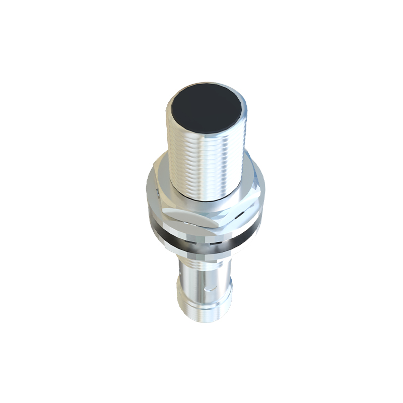
Furthermore, certain smart sensors with IO-Link or other digital communication capabilities use the indicator light to show communication status. A slow, rhythmic pulse might indicate successful parameterization and active data exchange, while an irregular flicker could denote communication errors or network conflicts. In teach-in mode, used for setting sensing thresholds or timers, the light will enter a distinct pattern (e.g., alternating colors) to guide the user through the configuration process.
For electrical engineers, integrating this visual diagnostic tool into standard operating procedures enhances system robustness. During routine checks, a quick visual scan of sensor banks can identify outliers—a sensor with a solid red light amidst a sea of steady greens immediately flags a problem. It allows for predictive maintenance; a sensor whose indicator begins to behave erratically under normal conditions might be failing or suffering from environmental contamination like metal dust accumulation on an inductive sensor's face.
In conclusion, the humble indicator light on a proximity sensor is far more than a simple power-on beacon. It is a sophisticated diagnostic port, a setup assistant, and a real-time operational monitor. Mastering its visual language—understanding the significance of colors, steady states, and blink patterns—is a fundamental skill for any electrical professional. It transforms reactive troubleshooting into proactive system management, ensuring higher uptime, faster commissioning, and more reliable automation processes. Always prioritize reviewing the manufacturer's documentation, as the specific semantics of the indicator are the final authority for that device.