Disassembling a proximity sensor switch is a common task for maintenance technicians, electricians, and automation engineers. Whether for troubleshooting, repair, or understanding its internal configuration, proper disassembly is crucial to avoid damage and ensure reassembly integrity. This guide provides a systematic, industry-standard approach to safely take apart a typical inductive or capacitive proximity sensor.
Important Safety Precautions
Before any disassembly, always adhere to lockout-tagout (LOTO) procedures. Ensure the sensor and the entire associated system are completely de-energized and isolated from all power sources (AC/DC supply lines). Verify the absence of voltage using a multimeter. Allow sensors in high-temperature environments to cool. Wear appropriate personal protective equipment (PPE), such as safety glasses and gloves, especially when dealing with sensors from harsh industrial settings that may contain debris or metal shavings.
Tools and Workspace Preparation
Gather the necessary tools: a set of precision screwdrivers (flat-head and Phillips, often size PH0 or PH1), hex keys (Allen wrenches), needle-nose pliers, a soft-jaw vise or a non-marring work holder, and an anti-static mat if dealing with sensitive capacitive models. Prepare a clean, well-lit workspace. Have small containers or magnetic trays ready to organize screws and tiny components to prevent loss. Taking photos with your phone at each step is highly recommended for reference during reassembly.
Step 1: External Inspection and Identification
Examine the sensor housing. Note the model number, brand, sensing type (inductive, capacitive), output type (PNP/NPN, NO/NC), and connection style (cable outlet or quick-disconnect plug). Check for any visible damage, cracks, or signs of fluid ingress. This information is vital for sourcing replacements if needed and understanding the internal layout.
Step 2: Separating the Sensing Head from the Housing
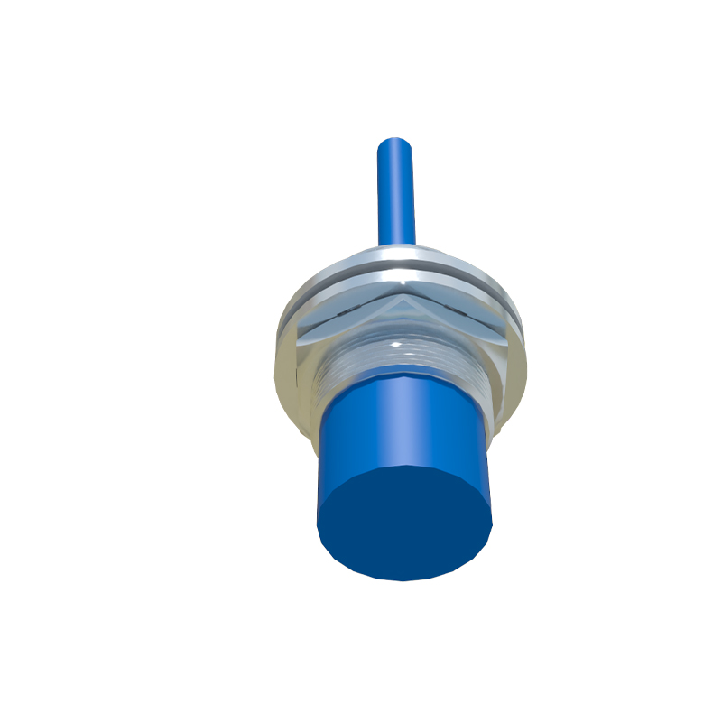
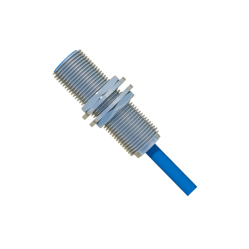
Many cylindrical proximity sensors (e.g., M8, M12, M18, M30 threaded barrels) consist of two main parts: the sensing face/head and the main body containing the electronics. These are often threaded together. Securely hold the main body (avoid gripping the sensing face directly) and carefully unscrew the front sensing head in a counter-clockwise direction. Some models may have a locking compound; apply steady, firm pressure. For rectangular or block-style sensors, the front face is usually integral to the main housing, secured by screws under a label or gasket.
Step 3: Accessing the Internal Electronics
Once the sensing head is removed (if applicable), locate the housing seam. The main body is typically sealed and may be ultrasonically welded, glued, or held by small screws. Look for screws, often concealed under manufacturer labels or rubber seals. Carefully peel back or puncture the label to access them. Use the correct screwdriver size to avoid stripping the heads. If no screws are visible, the housing may be a press-fit or snap-fit design. In such cases, gently insert a flat-head screwdriver into the seam and carefully twist to separate the halves, working your way around the perimeter. Avoid using excessive force to prevent cracking the plastic or metal shell.
Step 4: Internal Component Examination
With the housing open, the internal printed circuit board (PCB) assembly will be visible. Observe how it is seated. It may be potted in epoxy or silicone for environmental protection. Non-potted units are easier to service. Note the orientation of the PCB before removal. The board is typically connected to the sensing coil (in inductive sensors) or electrode plate (in capacitive sensors) at the front and to the output wires or connector pins at the rear. There might be small retaining clips or screws holding the PCB in place. Document the wire color coding and their solder points.
Step 5: PCB and Core Component Removal
If necessary to remove the PCB, first de-solder the wires connecting it to the external cable or terminal block. Use a soldering iron with appropriate heat and a solder sucker or wick. Label each wire. For sensors with integrated connectors, the PCB may simply plug into a header. Gently release any clips and lift the board out. The sensing element—a coiled ferrite core for inductive types—is usually press-fitted or glued into the front housing. Do not attempt to remove it unless absolutely necessary, as it is a calibrated component. Damage here typically renders the sensor irreparable.
Step 6: Cleaning and Inspection
With components disassembled, inspect for obvious faults: burnt components on the PCB, cracked solder joints, corroded traces, damaged coils, or broken wires. Clean any dirt, metal dust, or oil from the housing and sensing face using isopropyl alcohol and a soft brush