Laser sensor modules are critical components in modern industrial automation, offering high precision for distance measurement, object detection, and positioning tasks. Proper wiring is essential to ensure reliable operation, safety, and longevity of these devices. This guide provides a comprehensive overview of wiring laser sensor modules, focusing on common types used in industrial settings, including through-beam, retro-reflective, and diffuse reflection sensors.
First, understand the basic components of a typical laser sensor module. Most industrial laser sensors consist of a laser emitter, a receiver (or detector), and an electronic processing unit. They typically have three to five connection terminals: power supply (Vcc and GND), output signal (such as NPN/PNP open collector, push-pull, or analog outputs), and sometimes additional lines for configuration or diagnostics. Always refer to the manufacturer's datasheet for the specific pinout and electrical characteristics of your sensor model.
Power supply connections are fundamental. Most laser sensors operate on DC voltages, commonly 12-24V DC. Connect the positive terminal (Vcc) to the regulated DC power supply's positive output, and the ground (GND) to the power supply's negative terminal. Ensure the power supply voltage matches the sensor's rated range to prevent damage. Use shielded cables for power lines in electrically noisy environments to minimize interference. Polarity must be observed; reversing polarity can permanently damage the sensor.
Output wiring depends on the sensor's output type and the control system it interfaces with. For digital output sensors (e.g., for object detection), common configurations include NPN (sinking) and PNP (sourcing) outputs. For an NPN output, the load (such as a PLC input or relay) is connected between the output wire and the positive supply. When the sensor activates, it sinks current to ground, completing the circuit. For a PNP output, the load is connected between the output wire and ground. When activated, the sensor sources current from the positive supply. Always verify the compatibility with your PLC or controller input type.
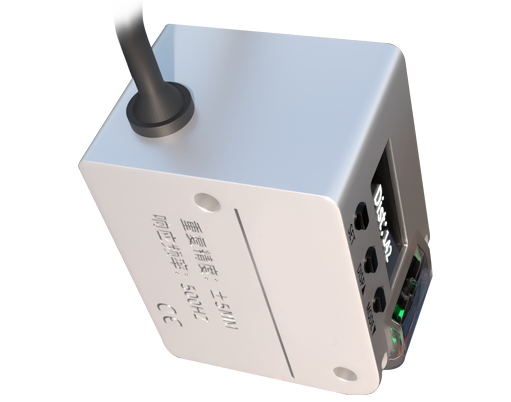
Analog output sensors (e.g., for distance measurement) typically provide a voltage (0-10V) or current (4-20mA) signal proportional to the measured distance. Wire the analog output to the corresponding analog input of your controller. For current outputs, a precision resistor may be required to convert the signal to voltage if the controller expects a voltage input. Ensure proper grounding and use twisted-pair cables to reduce noise on analog signals.
Safety precautions are paramount. Before wiring, disconnect all power sources. Laser sensors, especially Class 2 or higher, emit concentrated light that can be hazardous. Never look directly into the laser beam or point it at reflective surfaces. Use appropriate protective eyewear if necessary. Follow local regulations for laser device installation.
Shielding and grounding are critical for stable performance. Connect the cable shield to earth ground at one end only, typically at the control panel, to avoid ground loops. Keep sensor cables away from high-voltage lines, motor drives, or other sources of electromagnetic interference (EMI). If using long cables, consider voltage drop; for analog signals, use signal conditioners or amplifiers if the distance exceeds the sensor's specified capability.
After wiring, perform a systematic check. Power on the system and verify the sensor's indicator LEDs (if present) show normal operation. Test the sensor's response using a target object. For analog sensors, measure the output with a multimeter to confirm it scales correctly with distance. Adjust sensitivity or other parameters as per the manual. Document the wiring diagram for future maintenance.
Common pitfalls include incorrect voltage application, mixing NPN and PNP wiring schemes, inadequate shielding, and ignoring environmental factors like ambient light or dust. Always ensure the sensor is rated for the operating environment (e.g., IP67 for dust and water resistance if needed). Regular inspection of connections for corrosion or looseness is recommended as part of preventive maintenance.
In summary, proper wiring of laser sensor modules involves careful attention to power requirements, output configuration, shielding, and safety. By adhering to manufacturer guidelines and industrial best practices, you can achieve accurate and reliable sensor performance, enhancing the efficiency of automation systems.