Inductive proximity sensors are non-contact electronic devices designed to detect the presence of metallic objects without physical contact. Operating on the principle of electromagnetic induction, these sensors generate an oscillating electromagnetic field from a coil wound around a ferrite core. When a conductive metal target enters this active field, eddy currents are induced on the target's surface. This causes a measurable change in the oscillation amplitude or frequency within the sensor's internal LC tank circuit.
A typical inductive proximity sensor circuit comprises several key components. The core element is an oscillator circuit, often a Colpitts or Hartley oscillator, which generates a high-frequency electromagnetic field at the sensing face. This oscillator is connected to a coil, which acts as the sensing element. A demodulator circuit monitors the oscillator's signal. When a metal object approaches, the energy loss due to eddy currents reduces the oscillation amplitude. The demodulator converts this amplitude change into a DC voltage signal. This signal is then fed into a threshold detector or Schmitt trigger circuit, which provides a clean, digital output switch signal—typically an NPN or PNP transistor switching a load in the external circuit.
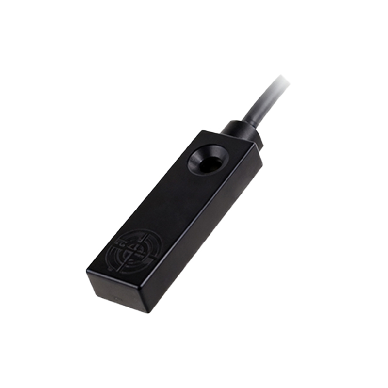
The design considerations for these circuits are critical for reliable operation. The oscillation frequency, usually between 100 kHz and 1 MHz, is chosen based on the target material and required sensing distance. Shielding is a vital aspect; shielded sensors have a metal ring surrounding the coil to focus the field axially forward, allowing flush mounting in metal. Unshielded sensors have a wider, lateral sensing field. The output stage is designed to interface with programmable logic controllers (PLCs) or other control systems, with common configurations being 3-wire DC sinking (NPN) or sourcing (PNP) outputs.
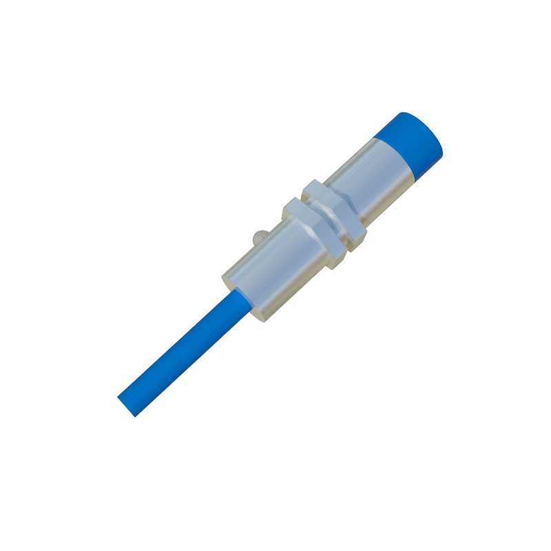
These sensors exhibit distinct performance characteristics. The sensing distance, or nominal range, is specified for a standard mild steel target. Factors like target size, shape, and material affect this range. For instance, steel is detected at 100% of the nominal range, while stainless steel might be detected at 85%, and aluminum or copper at 50% or less due to differences in electrical conductivity and magnetic permeability. The sensor's hysteresis—the difference between the switch-on and switch-off points—prevents output chatter when a target is at the exact sensing edge.
Applications for inductive proximity sensor circuits are vast across industrial automation. They are fundamental in position detection on assembly lines, counting metallic parts, monitoring rotational speed via gear teeth, and as end-of-travel limit switches in machinery. Their robustness, with solid-state designs having no moving parts, allows for long-term reliability in harsh environments with vibration, dust, or moisture. Modern variants include analog output models that provide a continuous signal proportional to distance, and specialized types immune to adjacent metal for precise mounting.
Understanding the circuit dynamics allows for proper selection and troubleshooting. Key parameters include the supply voltage (commonly 10-30V DC), output current capacity, switching frequency (how fast it can detect objects per second), and environmental ratings like IP67 for dust and water resistance. When installing, engineers must ensure the correct voltage polarity, adequate electrical noise suppression, and a proper gap between the sensor and its mounting bracket to prevent interference. By leveraging electromagnetic principles through precise circuit design, inductive proximity sensors provide a critical, reliable solution for automated metal detection.