In industrial automation and control systems, 3-wire proximity sensors are ubiquitous components, prized for their reliability, non-contact operation, and ability to detect metallic objects. Unlike their 2-wire counterparts, 3-wire sensors offer distinct advantages, including better switching performance and compatibility with a wider range of programmable logic controllers (PLCs) and other control devices. However, proper wiring is fundamental to their correct and safe operation. This guide provides a comprehensive, step-by-step approach to wiring a 3-wire DC proximity sensor, covering essential principles, common configurations, and crucial safety considerations.
First, it is imperative to understand the basic anatomy of a 3-wire DC sensor. You will typically find three distinct wires, each color-coded according to international standards (though always verify the manufacturer's datasheet). The most common color scheme is:
Brown Wire: This is the positive supply wire (+V). It connects to the positive terminal of your DC power source.
Blue Wire: This is the negative supply wire (0V or Common). It connects to the negative terminal of your DC power source.
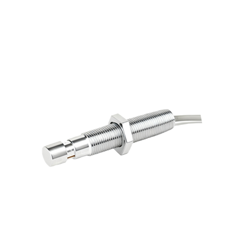
Black Wire: This is the output signal wire. The state of this wire (switched ON or OFF) changes when the sensor detects a target.
The output type is critical and must be matched to your load (e.g., a PLC input, relay coil, or indicator lamp). There are two primary output configurations:

1. NPN (Sinking) Output: In this configuration, the black output wire acts as a switch to connect the load to 0V (Negative). When the sensor is activated, it "sinks" current from the load to ground. The load must be connected between the positive supply (+V) and the black wire.
2. PNP (Sourcing) Output: Here, the black output wire acts as a switch to connect the load to +V (Positive). When activated, it "sources" current from the positive supply to the load. The load must be connected between the black wire and the negative supply (0V).
Step-by-Step Wiring Procedure:
Step 1: Safety First.
Always disconnect all power sources before beginning any wiring work. Lock Out, Tag Out (LOTO) procedures should be followed in industrial environments. Verify the sensor's operating voltage (e.g., 10-30V DC) matches your power supply.
Step 2: Identify Your Sensor Type.
Consult the sensor's label or datasheet to confirm whether it is NPN or PNP and its voltage rating. This information is non-negotiable.
Step 3: Connect the Power Wires.
Connect the brown wire to the positive (+) terminal of your DC power supply.
Connect the blue wire to the negative (- or 0V) terminal of your DC power supply.
Step 4: Connect the Output Wire (Black) and the Load.
This step differs for NPN and PNP sensors.
For an NPN Sensor:
One terminal of your load (e.g., PLC input terminal, relay coil) should be connected to the positive (+) supply rail.
The other terminal of your load is connected to the sensor's black wire.
Operation: When a target is detected, the NPN transistor inside the sensor turns on, connecting the black wire (and thus the load's terminal) to 0V (Blue wire), completing the circuit and energizing the load.
For a PNP Sensor:
One terminal of your load should be connected to the negative (0V) supply rail.
The other terminal of your load is connected to the sensor's black wire.
Operation: When a target is detected, the PNP transistor turns on, connecting the black wire (and the load) to the positive supply (+V, Brown wire), completing the circuit and energizing the load.
Step 5: Verify and Test.
Double-check all connections for tightness and correctness. Restore power. Use a non-metallic tool (like a plastic screwdriver) to bring a target metal within the sensor's sensing range. Observe the sensor's indicator LED (if present) and the response of your load (e.g., a relay clicking, an LED illuminating on the PLC). The sensor's datasheet will specify its sensing distance.
Common Wiring Diagrams & Important Considerations:
Shielded Cable: In electrically noisy environments, use a shielded cable. Connect the cable shield to a functional earth ground at the control panel end