In industrial automation and machinery, proximity sensors are indispensable components that detect the presence or absence of objects without physical contact. However, their reliable operation is frequently challenged by electromagnetic interference (EMI), crosstalk, and environmental factors. Shielding, therefore, becomes a critical design and installation consideration to ensure signal integrity, prevent false triggering, and extend sensor lifespan. This article delves into the principles and practical methods of effectively shielding proximity sensors.
The core challenge stems from the operating principle of many proximity sensors, particularly inductive and capacitive types. They generate electromagnetic fields to detect targets. In dense installations, the field from one sensor can interfere with its neighbor, a phenomenon known as crosstalk. Externally, sources like variable frequency drives (VFDs), welding equipment, power lines, and radio transmitters can generate EMI that disrupts the sensor's sensitive electronics, causing erratic behavior or complete failure.
Shielding strategies primarily address two paths of interference: radiated and conducted. Radiated interference travels through the air, while conducted interference enters through power supply or signal cables. A comprehensive approach tackles both.
1. Sensor Selection and Physical Shielding:
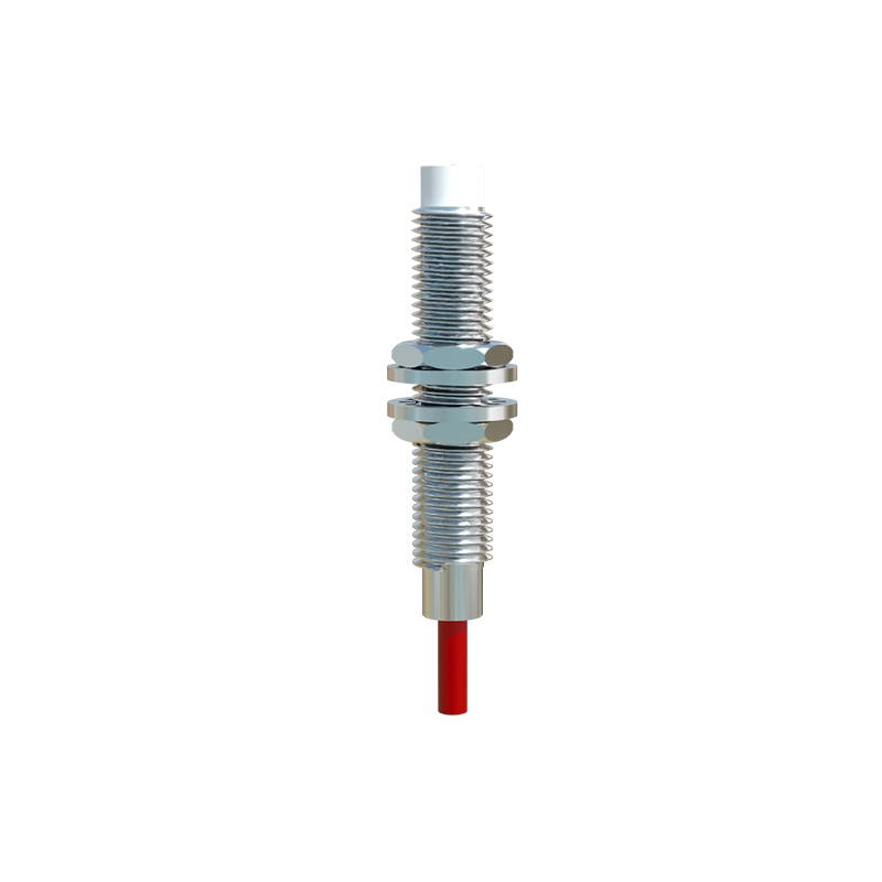
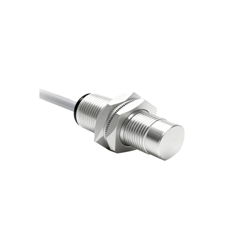
Many proximity sensors come with integrated metallic shrouds or "shielded" face designs. A shielded (or embeddable) sensor has its sensing field concentrated at the front face, allowing it to be flush-mounted in metal without triggering on the surrounding material. This very metal mounting provides a degree of natural shielding against lateral EMI. In contrast, non-shielded sensors require a clearance around them but can have longer sensing ranges. For high-interference environments, opting for inherently shielded sensor models is the first line of defense. Additionally, installing sensors within grounded metal enclosures or conduits offers excellent protection against external radiated noise.
2. Cable Management and Shielding:
The cable is often the most susceptible antenna for picking up interference. Using shielded cables is paramount. The shield, typically a braided copper mesh or aluminum foil, must be properly grounded. A critical best practice is to ground the cable shield at one end only, usually at the controller or system ground point, to avoid creating ground loops which can themselves induce noise. Cables should be routed away from high-power lines, motor leads, and other noise sources. When crossing power cables is unavoidable, do so at a 90-degree angle to minimize inductive coupling. Securing cables with cable ties and using cable trays or metal conduits further enhances protection.
3. Electrical Noise Suppression Techniques:
Ferrite Cores: Clamping ferrite cores or beads around sensor cables near the connection points can suppress high-frequency noise.
Separate Wiring: Always run low-voltage sensor signal cables and DC power supplies in separate conduits or trays from high-voltage AC power lines.
Filtering: Incorporating noise filters in the power supply line to the sensor system can clean conducted interference. Some advanced sensors have built-in filtering circuits.
Proper Grounding: Establish a single-point, robust system ground. Ensure all metallic enclosures, shields, and the sensor bodies (if specified) are connected to this ground with low-impedance paths. Avoid using conduit or structural metal as a primary ground path.
4. Installation Spacing and Configuration:
To prevent crosstalk between sensors, maintain the manufacturer's recommended minimum separation distance. This is especially crucial for opposing sensors. If space is limited, consider staggering their installation or using sensors operating at different frequencies. Adjusting the sensing distance (reducing sensitivity) to the minimum required for the application can also make the sensor less susceptible to picking up stray fields from nearby objects or sensors.
5. Testing and Diagnostics:
After installation, conduct thorough testing under all operational conditions, including with all machinery active. Use an oscilloscope to check for noise on the signal line if intermittent issues persist. Many modern programmable logic controllers (PLCs) can monitor signal stability, helping to identify noisy channels.
In conclusion, effective proximity sensor shielding is not a single action but a system-wide philosophy. It begins with selecting the right sensor type and extends through careful cable selection, disciplined routing practices, robust grounding, and thoughtful physical installation. By methodically addressing both radiated and conducted noise paths, engineers and technicians can create robust systems where proximity sensors perform reliably, maximizing uptime and productivity in even the most electrically hostile industrial environments. Ignoring these practices often leads to mysterious faults, costly downtime, and premature component failure.