In the world of industrial automation and electronic design, proximity sensors are ubiquitous. A common point of confusion, especially for those new to installation, revolves around the sensor's wiring, specifically the presence of leads of differing lengths. The question often arises: "Why does my proximity sensor have one long wire and one short wire?" The answer is not rooted in electrical function but in a crucial aspect of installation and safety: proper shielding and grounding.
At its core, a standard two-wire or three-wire DC proximity sensor is a simple device. It requires a power supply (typically 10-30V DC) and provides a switching output. Electrically, both the brown (positive) and blue (negative/common) wires are conductors of equal importance for completing the circuit. The physical difference in length is a deliberate design choice made by manufacturers.
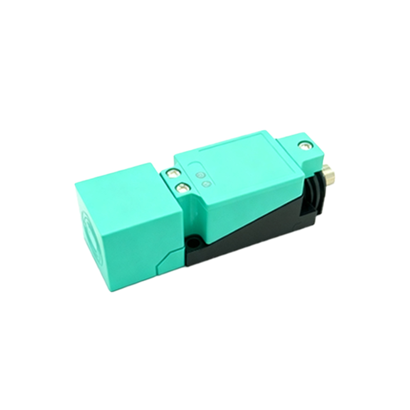
The primary reason for one lead being shorter is to enforce correct grounding practices for the cable shield. Most industrial-grade proximity sensor cables include a braided or foil shield, which is a conductive layer surrounding the inner power and signal wires. This shield's sole purpose is to protect the sensor's signal from electromagnetic interference (EMI) and radio frequency interference (RFI), which are plentiful in industrial environments filled with motors, drives, and welding equipment.
Here’s the standard procedure and the logic behind the lead lengths:
1. The longer lead is typically connected to the positive DC supply voltage (e.g., 24V).
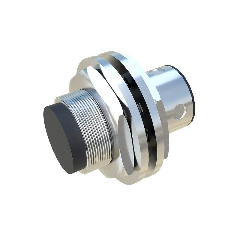
2. The shorter lead is connected to the negative or 0V DC line, which is also the system ground in most control cabinets.
3. The cable shield itself is not intended to be a current-carrying conductor. It must be grounded at exactly one point to drain away interference. The standard and safest practice is to ground it at the control cabinet end, not at the sensor end.
4. The shorter negative lead is designed to be connected first. Its length ensures that when you prepare the cable, the shield is naturally gathered and clamped to the grounding point (like a DIN rail clamp or a shielded connector) immediately after the negative wire is terminated. The longer positive lead then runs to its terminal without interfering with this grounding process.
This design physically guides the installer toward best practices. If the leads were the same length, it would be easier to ignore the shield or ground it improperly, such as at both ends, which can create ground loops. A ground loop is a condition where multiple ground paths create a circulating current, which can itself become a source of interference and lead to erratic sensor behavior or system noise.
Understanding this is critical for reliable operation. An ungrounded or improperly grounded shield is essentially useless. Interference can couple into the sensor's signal line, causing false triggers, missed detections, or unstable readings. In sensitive applications, this can lead to machine downtime, product defects, or safety issues.
When installing a sensor with asymmetrical leads, follow these steps:
Strip the cable jacket back sufficiently to expose the shield braid.
Terminate the short lead (usually blue) to the DC negative or common terminal.
Immediately use a suitable cable clamp or gland to securely crimp the exposed shield braid to the grounded metal panel or DIN rail. This should be done as close to the wire termination point as possible.
Finally, terminate the long lead (usually brown) to the DC positive terminal.
For a three-wire sensor, the black (or white) output wire will be of a length similar to the positive lead, and the same grounding principle applies.
In summary, the long and short leads on a proximity sensor cable are a form of "foolproof" engineering. They do not denote electrical polarity in terms of importance but serve as a physical reminder to properly ground the cable shield at the control panel. This simple design feature, when understood and followed, significantly enhances the sensor's immunity to environmental noise, ensuring stable, reliable performance and reducing maintenance headaches. Always consult the manufacturer's datasheet for specific instructions, but the principle of single-point shield grounding via the shorter lead remains an industry-standard practice.