In the complex and electrically noisy environments of modern industrial automation, proximity sensors are indispensable workhorses. They provide non-contact detection of objects, enabling precise control in machinery, robotics, and assembly lines. However, their reliable operation is frequently challenged by various forms of interference. Understanding the types of interference is the first critical step toward ensuring system robustness and minimizing costly downtime.
1. Electromagnetic Interference (EMI)
This is arguably the most common and pervasive threat. EMI originates from rapidly changing electrical currents and voltages, generating electromagnetic fields that can induce unwanted signals in sensor circuitry or its cabling.
Sources: Variable Frequency Drives (VFDs) controlling motors, welding equipment, solenoids, relay coils, and even other nearby sensors switching on/off are potent sources. Radio Frequency (RF) sources like walkie-talkies or cellular transmitters can also cause issues.
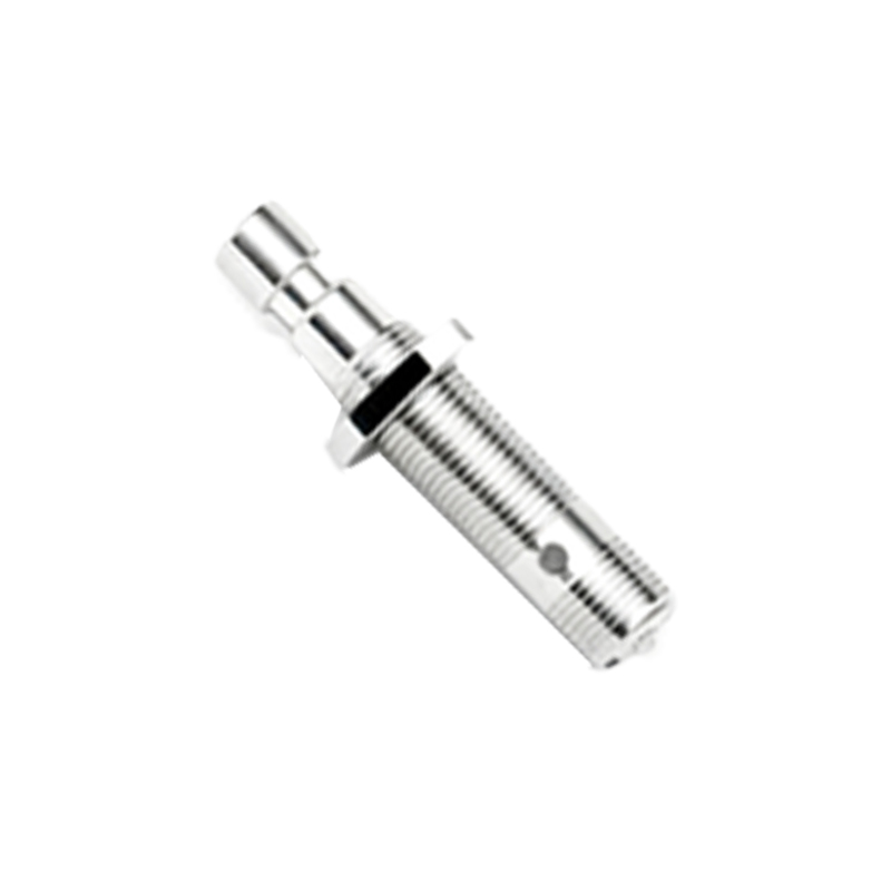
Effect on Sensors: EMI can cause false triggering (sensor detects an object when none is present), failure to detect an object, or erratic and unstable output signals. Inductive sensors, which rely on an oscillating electromagnetic field, are particularly susceptible.
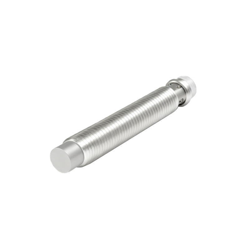
2. Cross-Talk (Sensor-to-Sensor Interference)
This occurs when two or more proximity sensors are mounted in close proximity to each other. The active electromagnetic field of one sensor can influence the oscillator of an adjacent sensor.
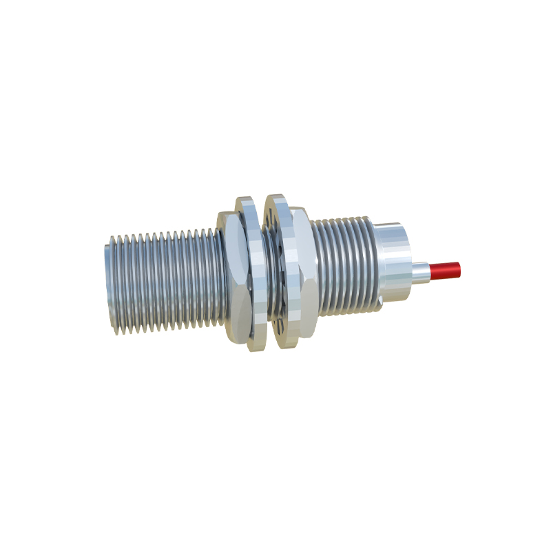
Sources: Parallel mounting of identical inductive sensors on a machine tool or a dense array of sensors on a packaging line.
Effect on Sensors: The influenced sensor may experience a shift in its sensing distance, become desensitized, or oscillate unpredictably. This is especially problematic when trying to detect small objects or maintain precise positional accuracy.
3. Electrical Noise on Power Supply Lines
The DC power supply line feeding sensors and controllers is not perfectly clean. Noise can be coupled onto these lines from other equipment sharing the same power circuit.
Sources: Switching of large inductive loads (motors, transformers), poor-quality switching power supplies, and ground loops.
Effect on Sensors: This conducted interference can disrupt the internal voltage regulation of the sensor, leading to erratic behavior or complete reset/failure. It often manifests as intermittent problems that are difficult to diagnose.
4. Physical and Environmental Interference
The sensing performance can be degraded by non-electrical factors related to the installation environment and target material.
Adjacent Metallic Objects ("Side-Mount" Effect): For inductive sensors, a fixed metal object (like a machine frame) within the lateral sensing zone can dampen the oscillator, reducing the effective sensing range forward of the sensor face.
Target Material Characteristics: The sensing distance of an inductive sensor varies significantly with the type of metal (steel, aluminum, copper, stainless steel). Capacitive sensors can be affected by the dielectric constant of the target material and by contaminants (dust, oil, moisture) building up on the sensing face, which may be misinterpreted as a target.
Temperature Extremes: Operating outside the specified temperature range can cause drift in the oscillator frequency of inductive sensors or affect electronic component performance, altering the switching point.
5. Mutual Interference in AC/DC Systems
In control panels where both AC and DC circuits coexist, improper wiring can lead to interference. A classic example is running AC power lines and DC sensor signal cables in the same conduit or cable tray.
Sources: AC power lines carrying 50/60 Hz or higher frequencies can induce a voltage in adjacent low-voltage DC signal lines through capacitive or inductive coupling.
Effect on Sensors: This induced noise on the signal line can be misinterpreted by the controller (PLC) as a valid on/off signal from the sensor, causing false logic states in the program.
Mitigation Strategies Overview
While a detailed mitigation guide is a separate topic, core countermeasures include:
Proper Sensor Selection: Choosing sensors with robust EMI immunity ratings, different operating frequencies to avoid cross-talk, or shielded models.
Correct Installation: Maintaining minimum separation distances between sensors, using shielded cables, and grounding the shield correctly at one end only (typically the controller end).
Power Supply Conditioning: Using filtered and regulated power supplies, sometimes with isolation transformers, to provide clean power.
Careful Wiring Practices: Physically separating AC power lines and DC signal cables, using twisted-pair cables for signals, and avoiding long, parallel runs of different cable types.
Environmental Consideration: Selecting sensors with appropriate ingress protection (IP) ratings and temperature specifications for the application environment.
By systematically identifying the type of interference present, engineers can deploy targeted solutions to shield these critical components from the invisible forces that threaten operational integrity. A proactive approach to interference management is not merely troubleshooting