Proximity switch sensors are fundamental components in modern industrial automation and control systems. As an electrical engineer with extensive field experience, I aim to provide a detailed, practical overview of these devices, covering their principles, types, selection criteria, and application best practices. This guide is written from an engineering perspective, focusing on the technical nuances that impact system performance and reliability.
At its core, a proximity sensor is a non-contact device that detects the presence or absence of an object within its sensing field without physical contact. This key characteristic eliminates mechanical wear and tear, enabling high-speed operation and long service life—critical factors in demanding industrial environments. The operating principle varies by type, but all generate an electromagnetic field or beam. When a target object enters this field, it causes a change in the field's state (e.g., oscillation amplitude, capacitance, magnetic flux), which is then converted by the sensor's internal circuitry into a clean, usable electrical output signal, typically a switching signal.
The primary categories of proximity sensors are Inductive, Capacitive, Ultrasonic, and Photoelectric. Inductive proximity sensors are the most common in metalworking and machinery. They generate an oscillating electromagnetic field and detect conductive metals, primarily ferrous metals like steel and iron. Their sensing range is relatively short, typically up to 60mm, and they are largely unaffected by non-metallic substances like dust, oil, or coolant, making them ideal for harsh machine tool environments. A key specification is the "correction factor" for different metals; for instance, stainless steel may reduce the nominal sensing distance.
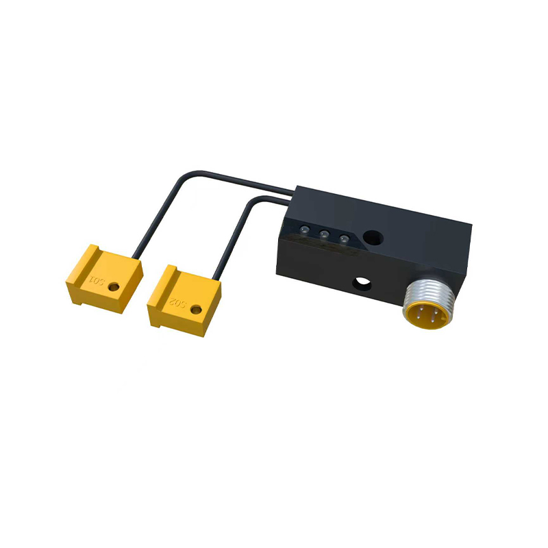
Capacitive proximity sensors can detect both metallic and non-metallic materials, including liquids, plastics, wood, and granules. They function by measuring changes in capacitance between the sensor's active face and the ground. This makes them perfect for applications like level detection in tanks (plastic or glass), material handling of paper or wood, and detecting filled vs. empty containers. They are sensitive to environmental factors like humidity and material composition, which must be considered during installation.
Ultrasonic sensors use sound waves beyond human hearing. They emit a pulse of ultrasonic waves and measure the time for the echo to return. This principle allows them to measure distance and detect objects regardless of color, transparency, or material (except highly sound-absorbent materials). They excel in applications requiring precise distance measurement, such as roll diameter monitoring, stacking height control, and liquid level sensing in challenging conditions like frothy surfaces.
Photoelectric sensors, while sometimes categorized separately, function on a proximity principle. They emit a beam of light (visible red, infrared, or laser) and detect its reflection or interruption. Diffuse reflective types act as true proximity sensors, detecting the reflection from the object itself. They are versatile for detecting a wide array of objects but can be influenced by color, reflectivity, and ambient light.
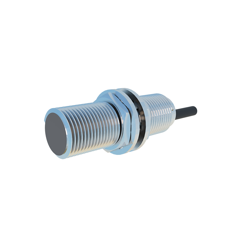
Selecting the right sensor requires a systematic approach. First, define the application: What is the target material? What is the required sensing distance? What is the operating environment (temperature, presence of chemicals, washdown requirements)? Next, consider the electrical requirements: Should the output be NPN (sinking) or PNP (sourcing) to match your PLC input? What is the required voltage range (10-30V DC is standard)? Don't overlook the housing material; stainless steel (e.g., V4A/AISI 316L) is essential for corrosive or food-grade environments, while nickel-plated brass suffices for general industry.
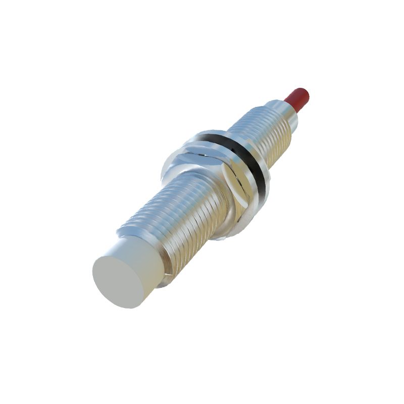
Installation and commissioning are where theory meets practice. Maintain the specified lateral and axial spacing between sensors to prevent mutual interference ("crosstalk"). For flush-mounted inductive sensors, ensure the surrounding metal is non-ferrous to avoid reducing the sensing range. Always refer to the sensor's technical data sheet for the "assured operating distance," which accounts for supply voltage and temperature tolerances, rather than just the "nominal sensing distance." For high-speed counting applications, verify the sensor's switching frequency against the target object's speed.
Troubleshooting common issues often involves a multimeter and a logical process. If a sensor fails to trigger, check the power supply, wiring polarity, and load current. Ensure the target object is within the assured operating distance and meets the material/size specifications. For erratic operation, investigate potential electrical noise from variable frequency drives (VFDs) or welding equipment; using shielded cables and proper grounding is crucial. Physical damage to the sensing face or housing is another common culprit.
The evolution of proximity sensors continues with the integration of IO-Link communication. This digital interface transforms a simple switch into an intelligent device capable of reporting parameters like operating distance, temperature, and switch cycle count for predictive maintenance. This aligns with Industry 4.0 initiatives, providing valuable data for optimizing processes and minimizing unplanned downtime.
In conclusion, proximity sensors are de