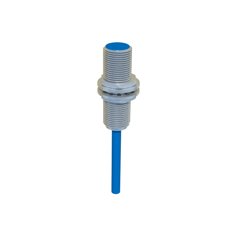
In the realm of industrial automation and machine design, proximity sensors are indispensable components for non-contact detection. While their electrical characteristics and sensing principles are often discussed, a deep understanding of their mechanical construction is equally critical for optimal selection, integration, and reliability. This article provides a detailed technical overview, supported by descriptions of typical mechanical structure images, to guide engineers in appreciating the physical design nuances of these devices.
Examining cross-sectional diagrams of common inductive and capacitive proximity sensors reveals a layered, purpose-built architecture. The front face, or sensing face, is invariably protected by a robust, often molded, plastic or metal housing. This material is carefully chosen based on the application environment—PBT (Polybutylene Terephthalate) for general chemical resistance or stainless steel for high-impact, washdown areas. Directly behind this protective barrier lies the core sensing element. In an inductive sensor, this is a coil wound around a ferrite core, connected to an oscillator circuit. The entire assembly is potted with a specialized epoxy resin, creating a hermetic seal that protects against vibration, moisture, and contaminants. This potting compound is a key mechanical feature, ensuring long-term stability and shielding the electronics from thermal and mechanical stress.
The housing design extends to incorporate threading, typically conforming to international standards like M8, M12, M18, or M30. These threaded barrels allow for secure mounting in drilled holes or sensor brackets. High-quality images often highlight the thread type (e.g., metric fine or coarse) and the presence of locknuts or hex nuts for anti-rotation. Some variants feature smooth cylindrical barrels with separate mounting brackets, offering flexibility in tight spaces. The rear of the sensor houses the connection interface. This can be a pre-wired cable exit with a strain relief gland—a critical mechanical component that prevents cable pull from damaging internal solder joints. Alternatively, a quick-disconnect (QD) style features a plug receptacle. The mechanical robustness of this connector, including its locking mechanism and IP (Ingress Protection) rating (e.g., IP67, IP69K), is a major factor in field reliability.
For specialized applications, mechanical variations are significant. Cylindrical sensors may have shielded (flush-mountable) or unshielded (non-flush) designs. A shielded sensor's sensing face is surrounded by a metal ring, allowing it to be mounted flush in metal without triggering false detection. An unshielded version has an extended sensing range but requires a non-metallic surround. Visual comparisons clearly show this metallic band. In contrast, rectangular or block-style sensors often feature multiple sensing faces and built-in mounting slots or holes. Their internal structure typically shows a larger PCB (Printed Circuit Board) layout, with components strategically placed to achieve the desired sensing field from one or more sides.
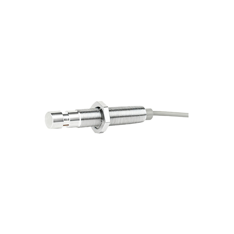
The mechanical integration of status indicators is another subtle yet important detail. Many sensors incorporate an LED (Light Emitting Diode) for power and switching state indication. The mechanical design must include a light pipe or a transparent window molded into the housing to make this LED visible. This component must be durable and maintain the sensor's sealed integrity. Furthermore, designs for high-temperature environments will show the use of high-temperature plastics, specialized seals, and possibly greater physical gaps between components to account for thermal expansion.
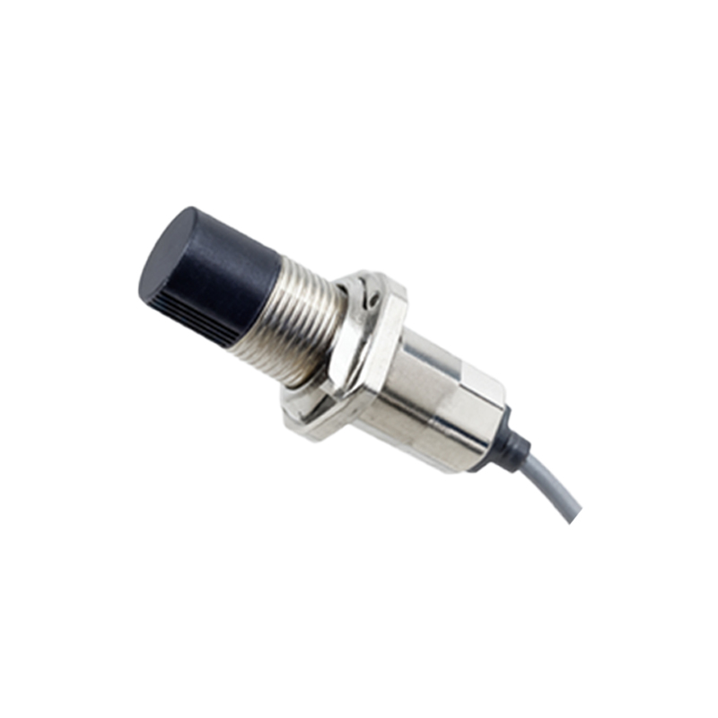
In essence, analyzing the mechanical structure of a proximity sensor goes beyond mere dimensions. It involves understanding the synergy between material science, sealing technology, connection methodology, and application-specific form factors. High-resolution cutaway images serve as essential tools, revealing how internal components are arranged and protected to withstand the harsh realities of industrial environments—from constant vibration and thermal cycling to exposure to oils, coolants, and particulate matter. A sensor's mechanical pedigree, evident in its construction, is a primary determinant of its mean time between failures (MTBF) and overall lifecycle cost. Therefore, engineers are advised to scrutinize these mechanical details as thoroughly as they would electrical specifications, ensuring the chosen sensor is structurally capable of performing reliably in its intended installation.