For electrical engineers and maintenance technicians working with industrial automation, accurately measuring the signal wire of a proximity switch sensor is a fundamental yet critical task. Proximity sensors, being non-contact devices, are widely used for position detection, object counting, and speed monitoring. Their reliable operation hinges on a correct and stable signal. This guide provides a detailed, step-by-step methodology for measuring the signal output, ensuring proper sensor functionality and integration into control systems.
Before beginning any measurement, safety is paramount. Always ensure the power to the sensor and the associated control circuit is disconnected, or follow appropriate lockout-tagout (LOTO) procedures for live measurement if absolutely necessary and with proper personal protective equipment (PPE). Identify the sensor type (e.g., inductive, capacitive) and its wiring configuration by consulting the datasheet. Typically, a 3-wire DC sensor will have brown (V+), blue (V- or common), and black (signal output) wires. For 2-wire sensors, the same two wires handle both power supply and signal switching.
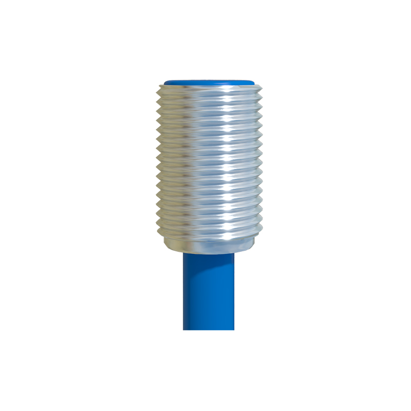
The essential tools for this task are a digital multimeter (DMM) capable of measuring DC voltage and continuity/resistance, and possibly an oscilloscope for dynamic signal analysis. Begin with a visual and mechanical inspection. Check the sensor body, sensing face, and cable for any physical damage, corrosion, or loose connections. Ensure the sensor is correctly mounted with the proper gap to the target as specified by the manufacturer.
For the core electrical measurement, follow these steps:
1. Power Off Continuity/Resistance Check: With power completely disconnected, set your DMM to the resistance or continuity mode. For a 3-wire NPN (sinking) sensor, measure between the black (signal) wire and the blue (common) wire. You should typically read a high resistance (e.g., several megaohms) when the sensor is idle (no target present). When a valid target is brought within the sensing range, the resistance should drop significantly, often to near zero ohms, indicating the internal switching transistor is closed. For a PNP (sourcing) sensor, measure between the brown (V+) and black (signal) wire. A 2-wire sensor's resistance will change similarly between its two wires when activated. This test verifies the basic switching action of the sensor.
2. Power On Voltage Measurement: Reconnect the sensor to its specified power supply (e.g., 10-30V DC). Set your DMM to measure DC voltage. For a 3-wire sensor:
NPN Type: Connect the black meter lead to the blue (common/0V) wire. Probe the black (signal) wire with the red meter lead. With no target, you should measure a voltage close to the supply voltage (e.g., 24V), indicating a high signal state (open collector). When a target is present, the voltage should drop to near 0V (low signal state).
PNP Type: Connect the black meter lead to the blue (common/0V) wire. Probe the black (signal) wire with the red meter lead. With no target, you should measure near 0V. When a target is present, the voltage should rise to near the supply voltage.
Load Verification: It is crucial to measure the signal voltage at the load (e.g., PLC input terminal). Sometimes, a voltage drop across long cables or a faulty connection can cause a correct sensor output to read incorrectly at the controller. Compare the voltage at the sensor's signal wire and at the PLC input point.
3. Dynamic Analysis with an Oscilloscope (if needed): For diagnosing intermittent faults, switching speed issues, or noise problems, an oscilloscope is invaluable. Connect the scope probe to the signal wire and the ground clip to the common/0V. Observe the signal waveform when a target repeatedly enters and leaves the sensing field. The rising and falling edges should be clean and sharp. Excessive noise, ringing, or slow switching times can indicate problems with wiring, shielding, or sensor health.
4. Current Measurement (Less Common): In some diagnostic scenarios, measuring the output current can be helpful. This requires breaking the signal circuit and placing the DMM in series in current measurement mode. Ensure the meter's current fuse is rated for the expected load. A reading significantly outside the sensor's datasheet specification may indicate an internal fault or an overloaded output.
Common pitfalls include measuring without a proper load connected (some solid-state outputs require a minimum load to function correctly), confusing NPN and PNP wiring, ignoring cable capacitance in long runs affecting switching speed, and not accounting for residual