In the realm of industrial automation and electrical engineering, proximity sensors stand as critical components for non-contact object detection. Among various target materials, Polyoxymethylene (POM), a high-performance engineering thermoplastic, presents unique challenges and considerations. This article delves into the principles, selection criteria, and application best practices for using proximity sensors specifically for POM detection.
POM, commonly known as acetal or Delrin, is valued for its high stiffness, low friction, and excellent dimensional stability. However, its material properties significantly influence the performance of inductive and capacitive proximity sensors, the two primary types used in industrial settings. Understanding this interaction is paramount for reliable system design.
Fundamental Operating Principles and POM Interaction
Inductive proximity sensors generate an electromagnetic field. They detect the presence of conductive metals by inducing eddy currents in the target, which dampens the sensor's oscillation. Crucially, standard inductive sensors are inherently unsuitable for detecting pure POM, as it is a non-conductive, non-metallic polymer. They will not recognize POM components. For applications requiring detection of POM parts in a metallic environment (e.g., verifying a POM gear is present on a steel shaft), specialized inductive sensors with enhanced sensitivity can sometimes detect the absence of metal, but this is an indirect method.
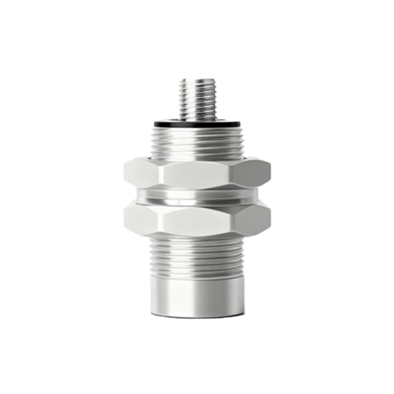
Capacitive proximity sensors, on the other hand, operate by generating an electrostatic field. They can detect any material that alters the dielectric constant in the sensing field, including plastics, liquids, and granules. Therefore, capacitive sensors are the primary and most effective choice for directly detecting POM components. The sensor detects the difference between the dielectric constant of air (≈1) and that of POM (typically between 3.7 and 4.0). This measurable change in capacitance triggers the sensor's output.
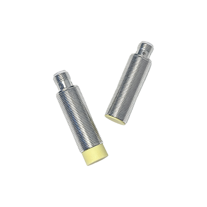
Key Selection Criteria for POM Detection
1. Sensor Type: Unambiguously, a capacitive proximity sensor is required for reliable direct detection of POM.
2. Sensing Distance: The nominal sensing distance (Sn) listed in datasheets is usually calibrated for a steel target for inductive sensors and for water for capacitive sensors. For POM, the effective sensing distance (Sr) will be reduced. A derating factor must be applied. For a capacitive sensor, the real sensing distance for POM can be estimated as: Sr(POM) ≈ Sn (√(ε_POM) / √(ε_water)), where ε is the dielectric constant. Given POM's ε is lower than water's (≈80), the sensing range will be substantially shorter. Engineers must consult sensor-specific derating curves.
3. Sensor Design and Shielding: Shielded (flush-mountable) capacitive sensors offer a more focused sensing field, making them less susceptible to interference from adjacent metal mounts or backplane material. Non-shielded (non-flush) sensors have a longer range but a wider field, which can lead to false triggering. For mounting in metal, shielded types are almost always mandatory.
4. Output Configuration: Choose between PNP (sourcing) or NPN (sinking) DC outputs, or AC outputs, based on the control system (PLC, relay) input specifications. Solid-state outputs are preferred for high-speed counting applications of POM parts on a conveyor.
5. Environmental Robustness: The sensor must withstand the operational environment. Consider IP ratings for dust and moisture protection (e.g., IP67), temperature ranges, and resistance to chemical exposure, which may include coolants or lubricants present in machining centers processing POM.
Application Best Practices and Troubleshooting
Mounting: Ensure stable mechanical mounting to prevent vibration-induced signal fluctuation. Maintain the recommended clearance around shielded sensors to prevent side-effects from adjacent metal.
Calibration and Adjustment: Most capacitive sensors feature a potentiometer for sensitivity adjustment. After installation, adjust the sensitivity so the sensor reliably detects the POM target at the required distance but does not trigger on background interference (like dust or humidity variations).
Target Consistency: Variations in POM formulation (e.g., different fillers like glass fibers or PTFE) can alter its dielectric constant. It is advisable to test the sensor with the actual production material.
Dealing with Thin Films/Small Parts: Detecting very thin POM films or tiny components challenges the sensor's capability due to the minimal mass affecting the field. Selecting a sensor with high baseline sensitivity and a small, focused sensing face is crucial.
Common Issues:
False Triggers: Often caused by airborne contaminants (oil mist, dust), moisture condensation on the sensor face, or interference from moving metal nearby. Improve sealing, use sensors with environmental compensation, or increase the hysteresis setting if available.