In industrial automation and control systems, proximity sensors are widely used for non-contact detection of metallic or non-metallic objects. One common configuration in complex circuits is the series connection of multiple proximity sensors. This article provides a detailed, engineer-oriented guide to the series wiring method, complete with a clear diagram and practical considerations.
A series connection involves linking multiple proximity sensors in a sequence where the same current flows through each sensor. This setup is often employed to create a logical AND condition in safety circuits or multi-point monitoring systems. For instance, in a machine guarding application, two or more sensors may be wired in series to ensure all guards are properly closed before enabling machine operation.
Wiring Diagram Overview:
The typical series circuit for DC 3-wire PNP normally open (NO) proximity sensors is illustrated as follows:

1. Connect the brown wire (positive supply) of the first sensor to the DC power supply positive terminal.
2. Link the black wire (output) of the first sensor to the blue wire (negative/ground) of the second sensor.
3. Connect the brown wire of the second sensor to the black wire of the first sensor (forming the series chain).
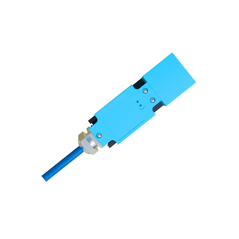
4. Finally, attach the black wire of the last sensor in the series to the load (e.g., PLC input, relay coil), and connect the blue wire of the first sensor directly to the DC power supply negative terminal.
For NPN sensors, the wiring logic is reversed, with the black output wire typically connected to the load toward ground.
Key Electrical Characteristics:
When sensors are connected in series, the total voltage drop across the chain is the sum of individual sensor voltage drops. Ensure the power supply voltage meets the cumulative requirement. Additionally, the current rating must not exceed the lowest-rated sensor in the series. Most industrial proximity sensors have a voltage range of 10-30V DC and a leakage current below 1.5 mA, which can affect performance in long series chains.
Advantages of Series Connection:
- Enhanced safety: All sensors must be activated to complete the circuit, reducing false triggers.
- Simplified wiring: Reduces the number of input points required on a controller.
- Cost-effective: Lowers installation and hardware costs by minimizing PLC modules or relays.
Practical Considerations and Troubleshooting:
1. Compatibility: Use sensors with similar specifications (e.g., all PNP or all NPN) to avoid circuit conflicts. Mixed types can cause malfunction.
2. Voltage Drop Calculation: Sum the voltage drops of each sensor at operating current. If the total approaches the supply voltage, consider using a higher voltage supply or limiting the number of sensors.
3. Diagnostic Indicators: Modern sensors with LED status lights simplify troubleshooting. In a series setup, a faulty sensor will break the circuit, indicated by all downstream sensors losing power.
4. Environmental Factors: In high-vibration or corrosive environments, secure connections with crimp terminals and protective conduits to prevent intermittent faults.
Common Applications:
- Conveyor belt systems where multiple sensors detect item presence at critical points.
- Robotic cell safety interlocks requiring confirmation of multiple guard positions.
- Assembly line quality checks using sequential sensor triggers.
In summary, series wiring of proximity sensors is a reliable method for creating interdependent detection zones. Always refer to manufacturer datasheets for specific ratings and test the circuit under simulated operational conditions. Proper implementation ensures robust performance, meeting both functional and safety standards in industrial automation.