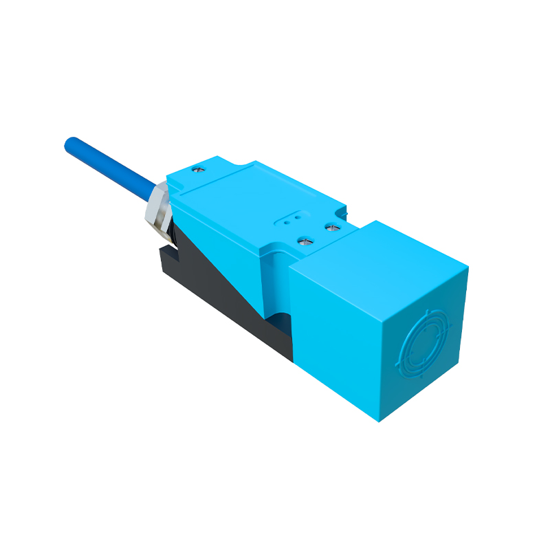
Inductive proximity switch sensor controllers are fundamental components in modern industrial automation, offering non-contact detection of metallic objects. Their robust design, reliability, and versatility make them indispensable in manufacturing, packaging, material handling, and robotics. This article delves into the operational principles, key features, application scenarios, and critical selection criteria for these essential devices.
At the core of an inductive proximity sensor is an oscillator circuit that generates a high-frequency electromagnetic field from its active face. When a metallic target enters this field, eddy currents are induced on the target's surface. This causes a change in the oscillation amplitude within the sensor, which is detected by a threshold circuit. The controller, often integrated or a separate unit, processes this signal to provide a clean, amplified output—typically a switching signal (PNP/NPN, NO/NC) or an analog value proportional to the sensing distance. The controller's role is crucial: it conditions the sensor's raw signal, provides power regulation, incorporates timing functions (like on-delay or off-delay), and interfaces with higher-level systems such as PLCs (Programmable Logic Controllers).
Key technical specifications define a sensor-controller system's performance. The sensing distance, or nominal range, is specified for a standard mild steel target. Factors like target material, size, and shape influence the effective range; for instance, stainless steel may reduce it, while copper or aluminum reduces it further. Switching frequency denotes how many on/off cycles per second the device can handle, critical for high-speed applications. Another vital parameter is hysteresis, the difference between the switch-on and switch-off points, which prevents output chatter when a target is at the sensing edge. Environmental robustness is ensured by high Ingress Protection (IP) ratings (e.g., IP67, IP69K) against dust and water, and robust housing materials like nickel-plated brass or stainless steel to withstand mechanical stress, cutting fluids, and washdowns.
Applications are vast. In conveyor systems, they count, sort, or detect the presence of metal parts. In machine tools, they serve as end-position limit switches for slides or spindles. In automated assembly, they verify the presence of components like screws or metal brackets. Safety interlifts on guards often employ them to ensure doors are closed before machine operation. A specialized application is in cylinder position sensing, where sensors detect the piston's position via a built-in magnet or a metallic piston itself.
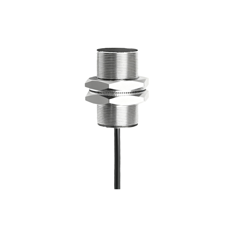
Selecting the right inductive proximity switch and controller requires careful consideration. First, identify the target material (ferrous or non-ferrous) and the required sensing distance, choosing a sensor with an appropriate nominal range and a safety factor. The sensor's form factor—barrel-style (threaded cylindrical), rectangular, or ring-shaped—must fit the mechanical installation. Electrical characteristics are paramount: choose the correct operating voltage (commonly 10-30V DC or 20-250V AC), output type (sourcing PNP or sinking NPN for DC models), and output configuration (normally open or normally closed). The controller selection hinges on the needed functionality: basic models simply provide power and signal conversion, while advanced units offer programmable logic, multiple sensor inputs, relay outputs, and communication protocols like IO-Link for diagnostic data (e.g., switch point monitoring, temperature, operating hours). For harsh environments, ensure the combined sensor and controller assembly has a suitable IP rating and temperature rating. Finally, consider electrical noise immunity and protection against short-circuits and overloads, which are often built into quality controllers.
Installation and maintenance best practices ensure longevity. Maintain the recommended clearance around the sensor's sensing face from surrounding metal (typically 1-2 times the sensor diameter) to prevent false triggering. Ensure proper wiring according to datasheet diagrams, using shielded cables in electrically noisy environments. Regular checks should verify the sensing face is clean from debris like metal chips or oil buildup, which can attenuate the sensing field. Modern controllers with diagnostic LEDs or IO-Link capabilities simplify troubleshooting by indicating power status, output activation, and potential faults.
In conclusion, inductive proximity switch sensor controllers form a reliable and efficient backbone for object detection in automation. Understanding their working principle, specifications, and integration requirements allows engineers to deploy them effectively, enhancing system reliability, safety, and productivity. As Industry 4.0 advances, the integration of smart sensors with advanced controllers providing predictive maintenance data will further solidify their critical role in the connected factory.